Printable Version of Topic
Click here to view this topic in its original format
914World.com _ 914World Garage _ Breather routing for 72 1.7L
Posted by: jcd914 Oct 3 2008, 02:30 PM
I have found several threads on breathers and a few hose routing diagrams but none seem to address the set up on my car.
I have a 1970 914 with (I am told) a 72 1.7L engine in it. It has a breathe set up that is closer to the 2.0L I have than the 71 1.7L I have.
The 72 1.7L has vent tubes in each head plumbed to the "tee" fitting next to the oil filler. From there the hose goes to the air cleaner (just like my 2.0L). The oil filler has a PCV valve (check valve) on it with a hose connected. I need to know how this hose should be plumbed. On my 2.0L it is connected to a nipple on the intake plenum. On the 72 1.7 it is tee'd (using a copper plumbing tee with pipes solder into it) into the charcoal canister hose going to the air cleaner.
I think this hose should be connected to the intake so fumes can be drawn in and burned in the engine but there are no available nipples on the intake close to the size of the hose. The largest nipple (probably the right size) connects to the Warm up regulator with a 1 inch long hose with no room for a tee fitting. The next largest (probably too small) is the hose going to the MAP sensor.
With a PCV valve and this hose connected to the air cleaner it serves no purpose since with out some suction nothing will pass the PCV valve.
My 71 1.7 does not have the vents in the heads and only has a fitting on the oil filler, no PCV valve.
Where should this hose connect?
Thanks
Jim
Posted by: toon1 Oct 3 2008, 03:50 PM
It should not be "t"d to the C canister line.
If you can take some pics, that would help.
Posted by: r_towle Oct 3 2008, 07:26 PM
on 72 Djet 1.7 the PCV hose goes to the plenum.
It goes to the fitting on the passenger side, closest to the rear of the car.
The fitting has a double divider rubber/metal fitting on it with two male end. One is for the PCV hose (red) and the other is for the Decel valve (small one)
Rich
Posted by: jcd914 Oct 3 2008, 08:39 PM
I will try to get some pics to post.
The plenum on this engine only has 1 fitting on the passenger side which is connected to the Manifold Pressure Sensor and it does not have a decel valve.
I believe I have 4 maybe 5 1.7/1.8 plenums and no 2 of them have the same configuration of nipples on them.
Is there supose to be any sore of restictor in the hose or fitting or does the PCV valve restrict the flow enough that it is not like a big vacuum leak?
Thanks for all the info 
Jim
Posted by: r_towle Oct 3 2008, 10:14 PM
There is no restrictor nor one way vacuum valve like water cooled cars.
Just pick a plenum and plug it in somewhere.
Or post a pick of the plenums, we can tell you which one is for a 1.7
Rich
Posted by: jcd914 Oct 4 2008, 06:14 PM

There is no restrictor nor one way vacuum valve like water cooled cars.
Just pick a plenum and plug it in somewhere.
Or post a pick of the plenums, we can tell you which one is for a 1.7
Rich
I was/am hoping to avoid changing the plenum since the engine is in the car still.
The PCV valve in the oil filler is a check valve, it only allows flow out of the crankcase.
Theoretic function of the system as I understand it:
At Low or No load: High intake vacuum would draw crankcase fumes into the engine thru the PCV valve in the oil filler, fresh air would be drawn into the crankcase thru the air filter via the hoses and tee fitting from the air cleaner to the ports in the heads.
At Part load: Low vacuum would some crankcase fumes into the engine thru the PCV valve in the oil filler, any excess fumes would flow to the air cleaner thru the hoses and tee fitting from the ports in the heads.
At Full load: All the crankcase fumes would flow to the air cleaner thur the hoses and tee fitting from the ports in the heads because there would be no vacuum to draw the fumes thru the PCV valve.
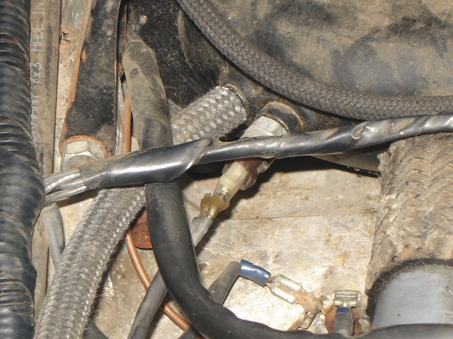
Here are a couple of pic of what is on my car now.
Only 2 hose nipples on the plenum, one for the Aux Air Valve (not shown in this pic)
And this one for the Manifold Pressure Sensor hose.
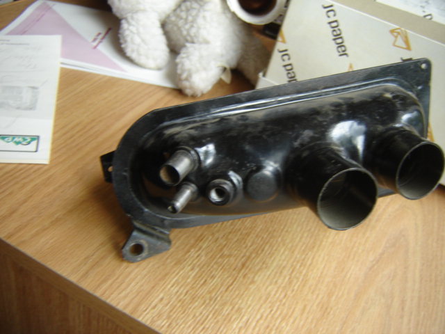
Here is another plenum with 2 extra nipples, 1 on this side and 1 one the other.
Thanks
Jim
Posted by: toon1 Oct 5 2008, 11:07 AM
Not quite sure what you are asking to do BUT, the threee ports viewed in the pic. of the plenum are,
Top left( bigger port) = PCV valve port
Bottom left, ( under the bigger port) = MPS.
Threaded hole+ ATS
The bigger port on the other side( not pictured) is for the AAR.
I have a 73 1.7, same hose routing. The PCV valve is plumbed to the large port on the pass. side of the plenum( the bigger port of what you have pictured) the vents for the heads , AFTER they are "t'd to the breather on the fan shround, go to a port on the air cleaner housing.
This is the hose routing you can find on Pelican parts web site.
Hope this helps
Posted by: jcd914 Oct 5 2008, 11:29 AM
Not quite sure what you are asking to do BUT, the threee ports viewed in the pic. of the plenum are,
I was hoping to find a way to hook up the breather hose to the plenum that is in the car, not switch out plenum with the one on my desk
Top left( bigger port) = PCV valve port
Bottom left, ( under the bigger port) = MPS.
Threaded hole+ ATS
The bigger port on the other side( not pictured) is for the AAR.
I have a 73 1.7, same hose routing. The PCV valve is plumbed to the large port on the pass. side of the plenum( the bigger port of what you have pictured) the vents for the heads , AFTER they are "t'd to the breather on the fan shround, go to a port on the air cleaner housing.
This fits the conclusion I was coming to. Since my 71 1.7 does not have the PCV valve and this "70" does I was confused. I will assume a PO (car has had a few) put the 72 engine in with the 70 plenum.
This is the hose routing you can find on Pelican parts web site.
I could not find a hose diagram for a 1.7L with a PCV valve at Pelican.
Hope this helps
It does, thanks.
Thanks to all for sharing their info.
Jim
Posted by: toon1 Oct 5 2008, 01:52 PM
Oh, Ok, now I get what you where asking. If you where to switch the air boxes, its' not that hard to do.
You should be able to find the hose routing diagram on PP site. If you go to the 914 page, there should be a menu on the left for tech articles, It should be in there.
Maybe someone here can add a link, i don't know how.
Posted by: r_towle Oct 5 2008, 04:05 PM
I would suggest in this order.
1) replace the plenum with the one in the pics that has more ports.
2) make a dual connection to the existin plenum for the PCV hose
3) get a breather box and drill out the pcv valve and use it as a drain for the breather box...
Rich
Powered by Invision Power Board (http://www.invisionboard.com)
© Invision Power Services (http://www.invisionpower.com)