Printable Version of Topic
Click here to view this topic in its original format
914World.com _ 914World Garage _ A different way to hook up 911 e-brakes
Posted by: Wes V Oct 4 2008, 07:07 PM
I think I've come up with a totaly new way to hook up 911 parking brakes. It involves making up longer hybrid cables.
It's not complex, doesn't cost tons, and is about as straight forward as possible.
It functions exactly as intended in the 911.
Here is a teaser photo;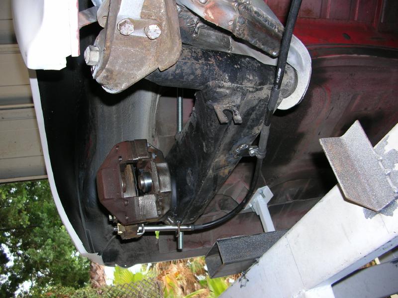
Here is a link to my write-up on how I did it (it's a preliminary write-up).
http://www.performanceforum.com/wesvann/914a/my-rear-brake/my-rear-brake.html
Wes
(can somebody please find me the photo that I've seen on this site where somebody used a cable end block at the parking brake lever that had set screws)
Posted by: okieflyr Oct 4 2008, 07:55 PM
Sweeeeet! ![popcorn[1].gif](style_emoticons/default/popcorn[1].gif)
Posted by: Wilhelm Oct 4 2008, 09:53 PM
Nice write up.
What are your ideas for the parking brake handle end of the cable?
Have you run across a source of cable ends and sheathing do your own custom cables?
Are new ends generally crimped on or silver soldered?
Posted by: LarryR Oct 4 2008, 10:09 PM
Very nice! I am getting ready to to the 911 brake swap with 911 ebrake and have been thinking a lot about the cables.
Larry
Posted by: Wilhelm Oct 4 2008, 10:38 PM

Nice write up.
What are your ideas for the parking brake handle end of the cable?
Have you run across a source of cable ends and sheathing do your own custom cables?
Are new ends generally crimped on or silver soldered?
So I'll reply to myself!!!!!!
After some web searching, looking especially at "dune buggy" companies, I'm finding all sorts of bits to shorten and put custom ends on cable. If possible I would like to make seamless cables brake-to-handle with the appropriate ends for my specific application.
Posted by: PRS914-6 Oct 4 2008, 11:17 PM
Nice write up. Most of us have thought of the idea but didn't care for the angle that the cable attaches to the e-brake because of the shape of the arm. You can't get a straight pull which has a tendency to pull the linkage.
The advantage of the bellcrank version is that you get to use the OEM cables and get a straight pull on the e-brake mechanism by offsetting the arm. Here is a pic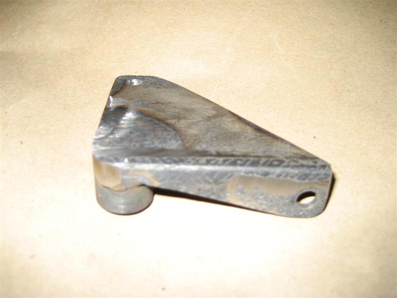
Posted by: Larry Hubby Oct 5 2008, 03:49 AM
Clever and resourceful, Wes. Looks good!
Larry
Posted by: PRS914-6 Oct 5 2008, 08:50 AM
Another thought on your idea........I don't have an arm here to look at but is there enough room to cut the arm (notch it) and weld a tube in its place with a straight shot to the mechanism? Also, I'm not sure but I'll look the next time my car is on the rack but there might be header interference with the cable out away from the arm...it's very close on a 6. Might need a tight 90 deg there.
You can draw a sketch of exactly what you want and send it to Terry cable and they will manufacture the cable perfectly as you like.
Posted by: Wes V Oct 5 2008, 11:27 AM
The issue with the bell-crank solution is that it only "pulls" on one of the speaders. I'm calling it an "issue" and not a "problem" due to the fact that several people have had good results with doing it this way.
As for anchorage of the cable at the parking brake lever, I'm going to work up something using set-screws. It's kind of a no-brainer and I'm not worried about it.
All of the end fittings I've seen in automotive installations are swedged (crimped) on.
Terrycable will do custom cables (according to Otto's in Santa Monica), but they are pricey.
Wes
Posted by: Wilhelm Oct 5 2008, 11:52 AM
The issue with the bell-crank solution is that it only "pulls" on one of the speaders. I'm calling it an "issue" and not a "problem" due to the fact that several people have had good results with doing it this way.
As for anchorage of the cable at the parking brake lever, I'm going to work up something using set-screws. It's kind of a no-brainer and I'm not worried about it.
All of the end fittings I've seen in automotive installations are swedged (crimped) on.
Terrycable will do custom cables (according to Otto's in Santa Monica), but they are pricey.
Wes
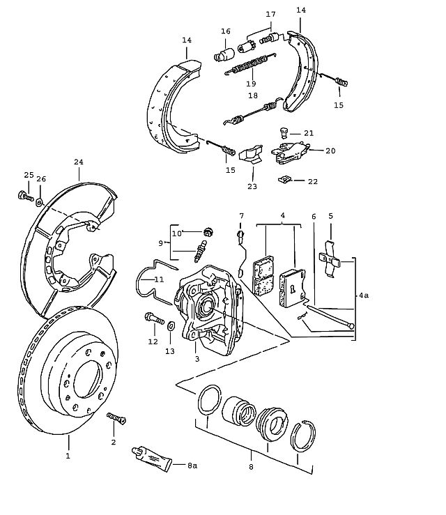
The 928,944, 924 mechanism requires only a pull, not compression of the spreader, and thus may be more suitable for the bellcrank crowd. The 928 shoes are the same size as the 944 and 911 and instead of having rivets for the spreaders to push on, have notches for the mechanism to lever on much like the brake shoes of american cars. The spreader is part 20 in this pic.
Posted by: jj83118 Oct 5 2008, 03:13 PM
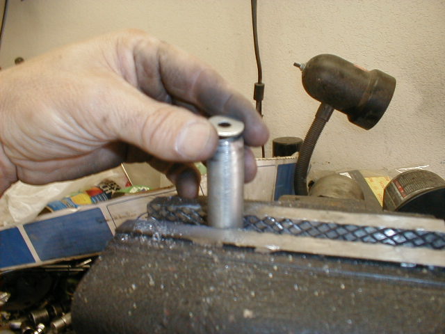
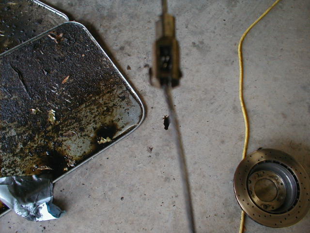
I was going to post my 911 e-brake cable solution, but I didn't get around to it until now.
I used two clutch cables and modified stock e-brake cable housings. I cut the pedal-end of the clutch cable off and shortened the threaded end a bit. Then I used a cut-off wheel to carefully remove the slotted ends of the stock e-brake cables off. If you make two long cuts 180 degrees apart, you can pry the crimped ends off for use later.
I used a short section of tubing that allowed a tight fit on the stock cable housings outer diameter and spot welded a short section of smaller tubing inside as a stop. This part plays double duty as a mount (all you need is to drill and tap a hole in the trailing arm).
I cut the housings to length first, then slid the clutch cables in to find the right length. After that, it is just a simple matter of re-crimping the ends on the cables and welding them (weld only on the crimped part into the cable).
I hope this all makes sense...I am including photos that better describe the process.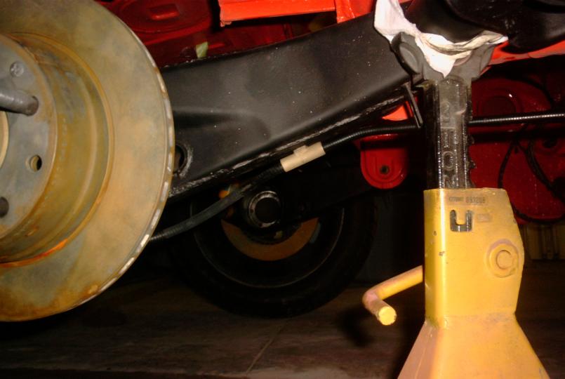
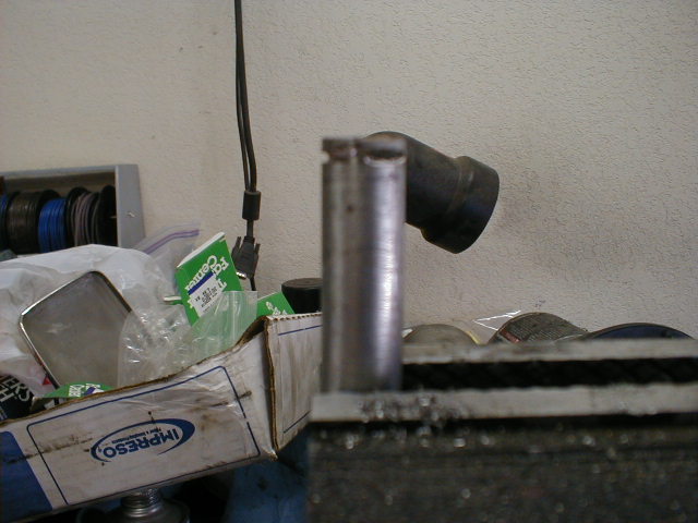
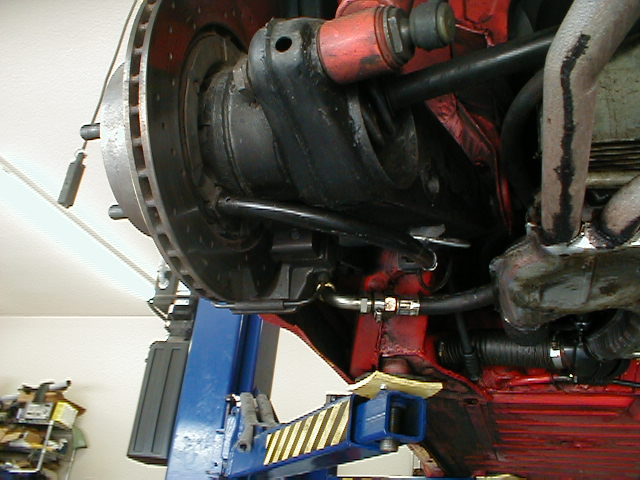
Posted by: jj83118 Oct 5 2008, 03:16 PM
Another shot from the inside.
Attached thumbnail(s)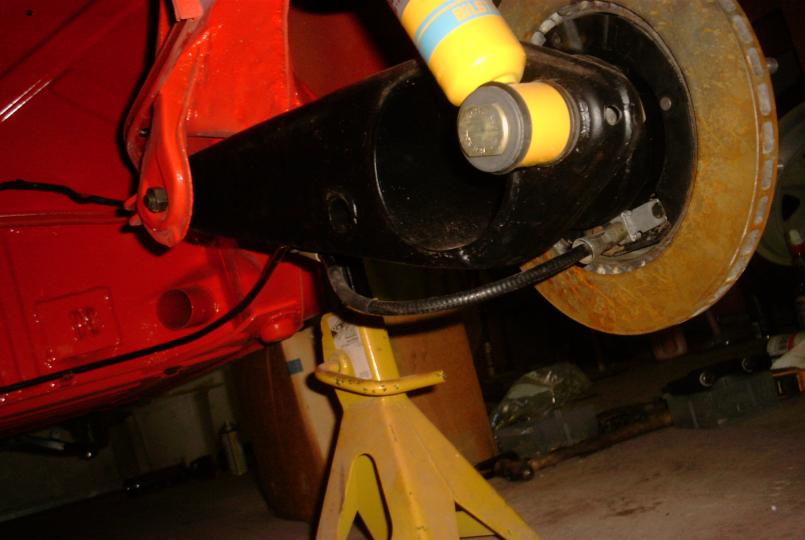
Posted by: jj83118 Oct 5 2008, 03:17 PM
Welded cable end.
Attached thumbnail(s)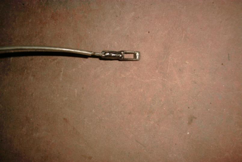
Posted by: jj83118 Oct 5 2008, 03:19 PM
A complete cable (still need to shorten the threaded end).
Attached thumbnail(s)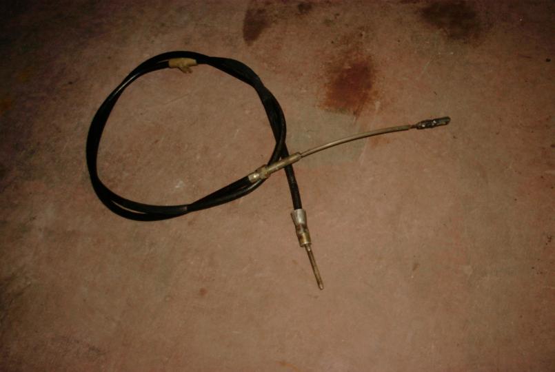
Posted by: Wilhelm Oct 5 2008, 04:50 PM
Welded cable end.
So when you cut this cable end, did you essentially split the tube and pull the old cable out? I take it you welded the cuts back together to remake a tube and then crimped this tube shut. Is Crimping always best? Does silver soldering the end onto the cable embrittle the end of the cable. I seem to remember 30 years ago a well driller reattaching his drillbit ends on 1" steel cable by brazing.
Posted by: sixnotfour Oct 5 2008, 04:54 PM
silver solder the way to go but crimping is way more effective.
never have tried the mig weld.
Posted by: Wes V Oct 5 2008, 06:17 PM
Welded cable end.
I like this!
I never thought it would be possible to remove and replace the end fitting.
What type of welder did you use? (mig or tig)
Wes
(dang photo isn't coming up)
Posted by: ClayPerrine Oct 5 2008, 07:06 PM
http://www.914world.com/bbs2/index.php?showtopic=88737 made me want to post this now. The problem I see (from experience) is the way the cable is routed in the other thread, you are going to melt it against the heat exchanger/header. It is just too close!!!
I came up with a different way to do the 911 park brake, using the stock 914 park brake cables.
First, buy some 1" conduit, and a conduit bender. Then bend the conduit until you have a 90 to 100 degree bend with a nice, gentle radius.
Weld the washer from the inboard end of the 911 park brake setup onto the end of the bent conduit. Drill a 1/8 inch hole in the outside of the tube, right at the end where the washer is welded. On the other end, cut 3 slots parallel with the end of the tube 1/16 inch from the end. 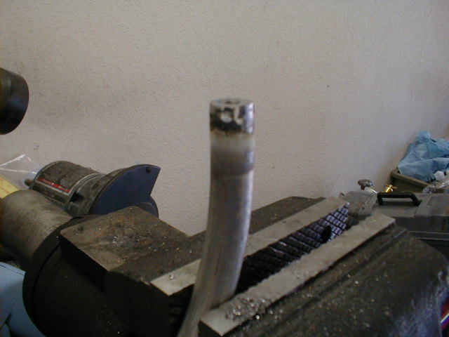
Take the 911 park brake cables that you got with the brakes, and cut them off. Pull out the inside, and make sure that you leave the cable long enough that it will reach the end of the tube when the threaded end is pushed through the hole in the washer. Braise up the cable end that was cut to keep it from fraying. 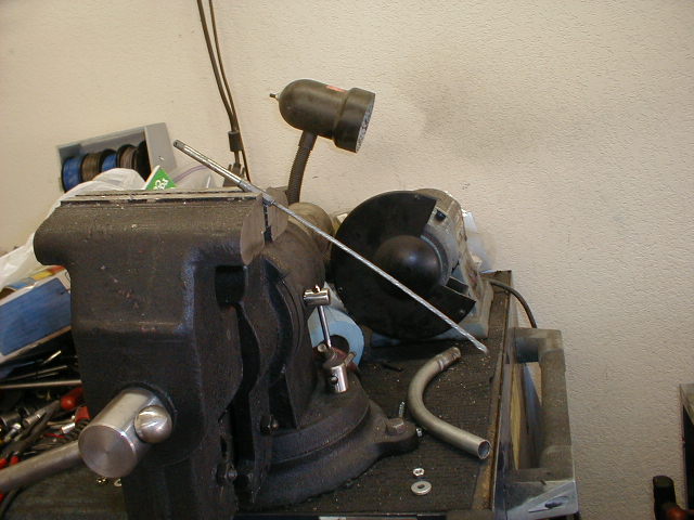
You can see the cutoff 911 park brake cable and the tubing in the background.
Then go to the hardware store and buy a couple of barrel nuts used for lawn mower cables. Measure the amount the rear end of the 914 park brake cable sticks out when it is disconnected from the handle and pulled all the way rearward. Drill out the clevis on the end of the 914 park brake cable so the barrel nut will go through it.
Put the barrel nut into the clevis on the end of the 914 park brake cable. Slip the braised end of the 911 park brake cable into the barrel nut. Tighten the barrel nut, then grind the barrel nut flush with the side of the clevis. Trim off the excess cable until you can make a straight cable out of the two joined cables.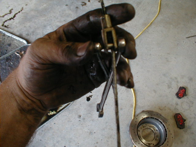
Put the now extended 914 park brake cable into the tube, and using the 1.8 inch hole in the side, push it through until you can pull the end out the center of the washer.
Put an E clip into the slots cut in the tube to hold it to the 914 park brake cable. Hook it up to the 911 park brakes on the back, and the handle on the front. Make sure the adjustment nuts are all the way back when you put the cables into the chassis on the handle ends.
Take the end of the tube and support it where the original park brake cable end goes using a 6x.10 bolt, 2 6mm fender washers, and a padded cable clamp. This allows the cable to flex to the side when you pull the park brake. 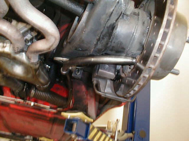
You can see from the pictures that the cables never come near the heat exchangers, and the park brake works great on my car!
Adjustment:
Adjust the shoes per the 911 service manual. When your shoes are adjusted correctly, then use the adjustment nuts on the cables to adjust the handle height when the brake is pulled.
I can take additional pictures of the brake setup, or you can see it in person at the Rocket City Ramble. Bring your Cameras!
Attached image(s)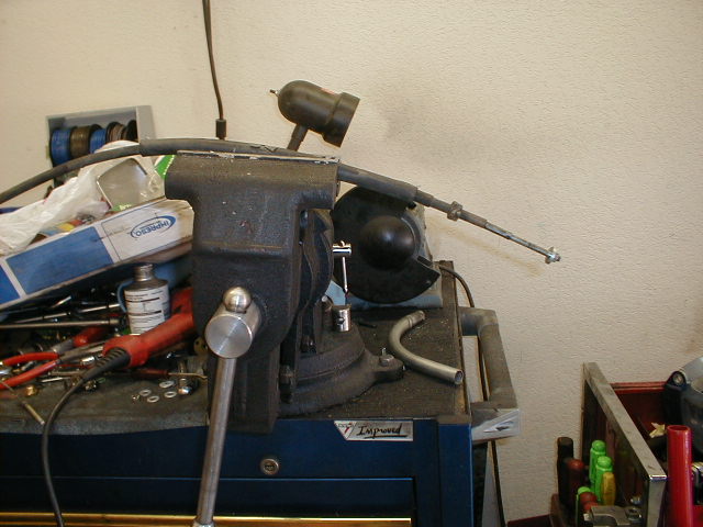
Posted by: Wes V Oct 5 2008, 08:09 PM
Clay;
The fact that what I did would place the sheathing close to the heat exchanger is a very valid consern!! My car is an on-going project and I don't know if it will be a problem at a latter date or not. (I'm planning an engine swap)
Most of the time that I post stuff, it's to get an idea out there. It seems to have worked due to a bunch of methods being brought up.
(I did think of making up the length of 1/2" stainless steel tube with a 90 degree bend, however the bender I have would have put too tight of a radius bend on it for what I was comfortable with)
Wes Vann
Posted by: ClayPerrine Oct 5 2008, 08:42 PM
Clay;
I'd have prefered that you just post this after the string I did. I'm not going to be offended.
The fact that what I did would place the sheathing close to the heat exchanger is a very valid consern!! My car is an on-going project and I don't know if it will be a problem at a latter date or not. (I'm planning an engine swap)
Most of the time that I post stuff, it's to get an idea out there. It seems to have worked due to a bunch of methods being brought up.
(I did think of making up the length of 1/2" stainless steel tube with a 90 degree bend, however the bender I have would have put too tight of a radius bend on it for what I was comfortable with)
Wes Vann
Ok.. I didn't want to hijack your thread. I can merge them for us.
My method is cheap, probably around 50 bucks all told.
I had a 911 park brake in my car since I got it running 3 years ago. I used custom cables at first, and I melted one on the heat exchanger. That is why I came up with this method. You, being a machinist, could probably do it better, but it works.
I know from looking at the cable radius yours is going to contact the heat exchanger/headers.
I need a stop for mine like you put in.
Posted by: jj83118 Oct 5 2008, 09:32 PM
I welded the crimped ends back on with a MIG welder and I did not weld all the way to the end. You don't want to weaken the cable.
I don't think I would attempt to silver solder or braze the ends as you will be fighting capillary action as the solder wicks its way up the cable.
I'll have to check header clearance once the engine is put back in my car (it's been out for quite some time now). If there is interference, I might be able to put an Adel clamp on the cable and attach it to the trailing arm.
Posted by: andys Oct 6 2008, 10:57 AM
Another thought on your idea........I don't have an arm here to look at but is there enough room to cut the arm (notch it) and weld a tube in its place with a straight shot to the mechanism? Also, I'm not sure but I'll look the next time my car is on the rack but there might be header interference with the cable out away from the arm...it's very close on a 6. Might need a tight 90 deg there.
You can draw a sketch of exactly what you want and send it to Terry cable and they will manufacture the cable perfectly as you like.
Wes,
Very nice write-up!
For you bell crank types, Wes came up with a very clever solution which employs a compound bell crank that provides opposing actions. He claims it's a bit too complex but, I disagree and think it's a unique solution and it allows the use of the stock e-brake cables. Wes, can you post some photos of this?
The one funamental problem with the 911 e-brake is getting a nice straight shot at the actuator. All the solutions place the cable at a slight angle; I don't know for sure how much of a real issue this is (perhaps none) but it "seems" less than ideal. Short of modifying the trailing arm, you're pretty much stuck with this as is.
Wilhelm, do you have a close photo of that 928 brake shoe spreader? Seems like it would simplify things quite a bit.
Andys
Posted by: Richard Casto Oct 6 2008, 12:49 PM
Wes,
Thanks for showing how you did this. I am still trying to decide how I am going to do this on my end.
Richard
Posted by: Richard Casto Oct 6 2008, 12:55 PM
The 928,944, 924 mechanism requires only a pull, not compression of the spreader, and thus may be more suitable for the bellcrank crowd. The 928 shoes are the same size as the 944 and 911 and instead of having rivets for the spreaders to push on, have notches for the mechanism to lever on much like the brake shoes of american cars. The spreader is part 20 in this pic.
I like the idea of the bellcrank approach because I would prefer to not make custom cables and would like to do this with off the shelf parts as much as possible. But I don't like how this does not compress the 911 spreader as it is supposed to. But the 928/944/924 pull mechanism sounds really interesting. Has anyone tried this yet?
Richard
Posted by: Wes V Oct 6 2008, 01:12 PM
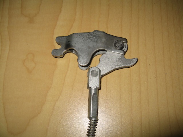
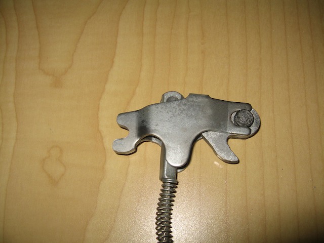
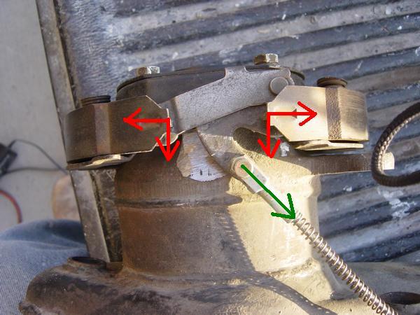
This is what AndyS is talking about when he comments on the "lever" design I did. He knew about it due to my sending him photos for discussion.
Prior to working up the method in my write-up, I did a couple designs that involved a lever action, which would still work the "push and pull" on the 911 spreaders.
I guess it's worth posting. (sorry about the first photo not being focused very well)
(Andy also voiced consern on the "cable method" being too close to the exhaust)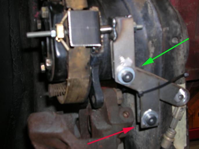
In order to figure out how it works you first off have to know that the allen head bolts are shoulder bolts and work as pivot points.
Then you have to know that the green arrow points to a "floating" pivot point. It isn't attached to anything other that the arms and can move in space.
The last thing is that the pivot point pointed to by the red arrow would be attached to the trailing arm. It's a "fixed" pivot point.
There is a short section of stainless steel tube that pushed on one of the spreaders, while a 1/4" thread rod pulls on the other.
Ya, it would work, but I just thought there had to be a less complex way to do it.
That black tie-wrap is just holding it in place for the photo.
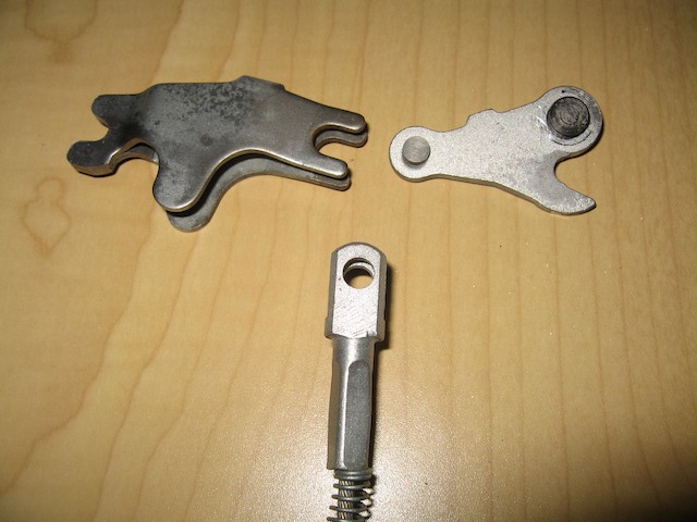
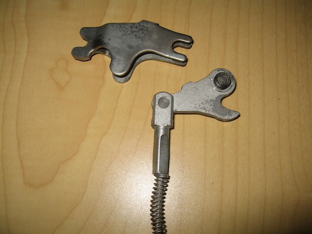
The following photos are showing the linkage on the garage floor, just to make it more clear.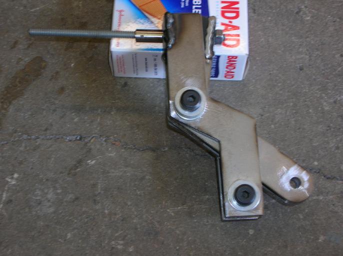
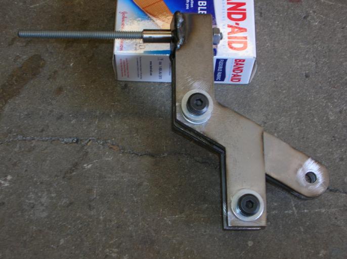
And the following photo shows the two arms.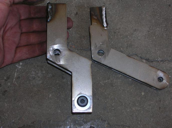
The one on the right fits inside the one on the left.
Both arms have a "bearing plate" on the end. The one on the left is what the length of tube bears on and also has a hole that the threaded rod can pass through. The one on the right is what the nut on the threaded rod bears on.
Discuss away!!
Wes Vann
Posted by: Richard Casto Oct 6 2008, 01:47 PM
Wes,
Thats pretty cool. Basically its just like the regular bellcrank solution, but that the pivot point for the bellcrank is not static. So the force on a normal bellcrank pivot would be against the arm (with pivot bolted or welded to the arm). But in this solution the bellcrank pivot is free to move, so that force is now applied to the other half of the spreader. In a way its much like a cable solution because the cable is free to move a bit as well.
I like it, but it is more parts, more fabrication and more things to go wrong. After looking at your solution I tried to sketch out some other ways to do it, but they basically result in something that is a bellcrank with a floating pivot and so far I can't think of something that is simplier than what you have.
One thing I haven't seen anyone try to re-engineer is the 911 spreaders. A drop in replacement for those parts that only requires you to pull would be interesting. I still wonder if the 924/944/928 spreader mentioned earlier will work or not.
Richard
Posted by: Wes V Oct 6 2008, 02:03 PM
Richard;
In light of the fact you can figure out how it works, you have got to be an Engineer!! It's kind of a mind trip because you have to thing about things floating in space and balancing forces.
I really don't think that there is a better "balanced bell crank" solution due to the physical restraints.
My first attempt was better, but wouldn't clear everything as I hoped.
You really have to build one to see how it clears stuff.
The 924 solution is interesting, but without having parts in front of you it's hard to say how possible it would be.
Here are things that come to mind;
You would have to swap the brake shoes and spreaders at a minimum.
Will the shoes fit on the 911 backing plate?
Are the shoes the same size. Or viewed another way, is the drum diameter the same?
You would have to modify the 911 backing plate to clear the spreader.
If it's possible to swap the complete assembly, the attachment bolt spacing would be wrong (larger bearings on latter cars). It may just be a matter of opening up the bolt holes.
I REALLY wish that I had a friend at a Porsche junk yard!
Wes
Posted by: Richard Casto Oct 6 2008, 03:43 PM
I am an Electrical Engineer by training, but I still remember my first year basic engineering classes (free body diagrams, etc.) that all the engineers had to take. 
You are right on all of your points regarding the 924 solution. Someone just needs to assemble the parts and see what can be done. If someone wants to send me the 924/944/928 parts, I will give it a try and report back! 
Posted by: Wes V Oct 6 2008, 05:15 PM
If someone wants to send me the 924/944/928 parts, I will give it a try and report back!
Dang, I was wishing the same thing.
I sure wouldn't mind somebody letting me have a -6 so I can verify exhaust clearances to the "cable" set-up. Of course, I'd need the 915 trans to mount it in place.
Wes
Posted by: Wilhelm Oct 6 2008, 08:25 PM
Another thought on your idea........I don't have an arm here to look at but is there enough room to cut the arm (notch it) and weld a tube in its place with a straight shot to the mechanism? Also, I'm not sure but I'll look the next time my car is on the rack but there might be header interference with the cable out away from the arm...it's very close on a 6. Might need a tight 90 deg there.
You can draw a sketch of exactly what you want and send it to Terry cable and they will manufacture the cable perfectly as you like.
Wes,
Very nice write-up!
For you bell crank types, Wes came up with a very clever solution which employs a compound bell crank that provides opposing actions. He claims it's a bit too complex but, I disagree and think it's a unique solution and it allows the use of the stock e-brake cables. Wes, can you post some photos of this?
The one funamental problem with the 911 e-brake is getting a nice straight shot at the actuator. All the solutions place the cable at a slight angle; I don't know for sure how much of a real issue this is (perhaps none) but it "seems" less than ideal. Short of modifying the trailing arm, you're pretty much stuck with this as is.
Wilhelm, do you have a close photo of that 928 brake shoe spreader? Seems like it would simplify things quite a bit.
Andys
Here they are:
All the parts seperated
Cable attached
Hooked to spreader
In the un-expanded mode
Again in the unexpanded mode attached to shoes
In the expanded mode attached to shoes (Note: the shoes are now farther apart)
The end for the parking brake cables for this application can be found here: http://www.aircraftspruce.com/catalog/appages/ms20667.php
This is what I'll be using with my trailing arms from another thread: http://www.914world.com/bbs2/index.php?showtopic=86910
Posted by: ClayPerrine Oct 6 2008, 09:53 PM
I actually looked at the 924/944 solution. The mount for the cable is integral with the backing plate, and to use that backing plate would require way more modification than I am willing to do. Plus it puts the calipers behind the trailing arms, and they then hit the shock mount bolt.
The 944 shoes will fit the 911 backing plates. If someone made a mount to hold the expander and the end of the cable, it would work.
But you are still left with custom cables.
Posted by: Wilhelm Oct 6 2008, 10:37 PM
I actually looked at the 924/944 solution. The mount for the cable is integral with the backing plate, and to use that backing plate would require way more modification than I am willing to do. Plus it puts the calipers behind the trailing arms, and they then hit the shock mount bolt.
The 944 shoes will fit the 911 backing plates. If someone made a mount to hold the expander and the end of the cable, it would work.
But you are still left with custom cables.
Easy deal is to use the stock 914 cable terminating where it normally does. Pull the inner cable out and put in a bus cable (longer) . Now run this cable back to a small pulley (sheeve for you mariners) to change direction right in back of the pull point for the 944/928 spreader which should be a 6 oclock when using the 911 backing plate. Crimp one of these suckers on to the end of the cable http://www.aircraftspruce.com/catalog/appages/ms20667.php. The most challenging fab would be welding a bolt on for the pulley. I'll post a pict when I'm done.
Posted by: ClayPerrine Oct 7 2008, 07:42 AM
I actually looked at the 924/944 solution. The mount for the cable is integral with the backing plate, and to use that backing plate would require way more modification than I am willing to do. Plus it puts the calipers behind the trailing arms, and they then hit the shock mount bolt.
The 944 shoes will fit the 911 backing plates. If someone made a mount to hold the expander and the end of the cable, it would work.
But you are still left with custom cables.
Easy deal is to use the stock 914 cable terminating where it normally does. Pull the inner cable out and put in a bus cable (longer) . Now run this cable back to a small pulley (sheeve for you mariners) to change direction right in back of the pull point for the 944/928 spreader which should be a 6 oclock when using the 911 backing plate. Crimp one of these suckers on to the end of the cable http://www.aircraftspruce.com/catalog/appages/ms20667.php. The most challenging fab would be welding a bolt on for the pulley. I'll post a pict when I'm done.
The spreader mechanism on a 944 mounts to the backing plate. The 944 backing plate will not fit a 914 trailing arm.
Where are you going to mount the spreader?
Posted by: Wes V Oct 7 2008, 11:03 AM
(I'm glad I started this sting)
Here's a bunch of thoughts and questions on the 944 spreader method (the "wilhelm" method).
In the stock configuration, does the spreader assembly just float free, held in compression by the shoes?
Looking back at the factory diagram posted by Wilhelm, what is item 23? What function does it serve?
When Clay says that the backing plate supports the cable, to be specific, is he taking about the "dead-head" anchoring of the sheathing. I'm pretty sure this is what he is saying due to sheathing having to be fixed in order for this to work. This is significant due to the fact that it wouldn't be required if a bell-crank was used (as in some of the other methods.
You couldn't use the VW bus cable due to it's end not being compatable. There just isn't any reason for it, other than being longer.
I have to assume that there is somthing like the 40mm spacer at the spreader, as there is on the 911, welded to the trailing arm.
Here is how I view it being done (if possible);
Use the early 911 backing plate and cut out the minimum to allow the 944 spreader to fit. Mount the shoes and spreader.
Fab up and weld in place the equivalent bracket as the 40mm one used in 911 installations. A hole would be needed for clearance for the "pull rod".
Use a bell-crank as shown in prior posts.
Connect the bell-crank to the spreader with a threaded rod and clevis. (NOT CABLE)
Remove and relocate (weld) the bracket that holds the stock 914 cable, directing it toward the bell-crank.
Attach the end of the stock 914 cable to the bell-crank using an "extension" arm as shown in prior posts, if required.
If all this works, I really like the solution. The fabrication work isn't that complicated and it would provide the most clearance from things like the exhaust piping.
I really wish that there was a 944 around here that I could take the rotors off and check it out, take measurements, and such.
Wes
Posted by: Wes V Oct 7 2008, 11:51 AM
I think it dawned on me why Clay said that the 944 spreader is "attached" to the backing plate.
I think it's that the backing plate prevents the spreader from being pulled outward by the cable.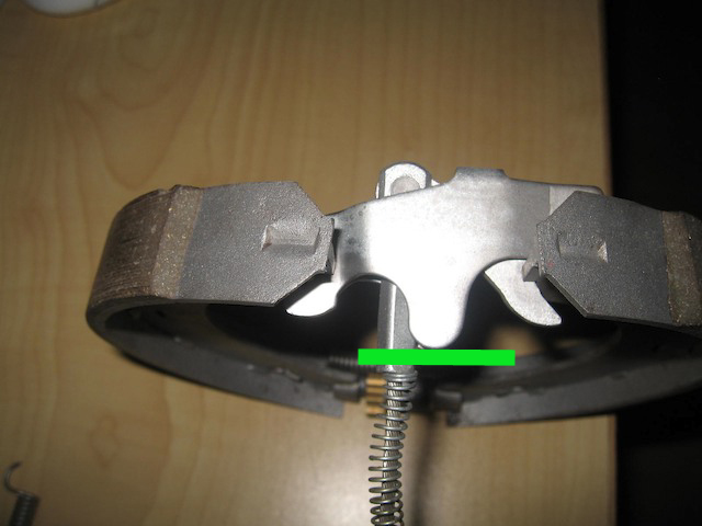
The green line would be the backing plate.
The spreader would "wipe" across the backing plate a small amount.
It may also help answer that that item 23 is.
If this isn't the case, then function wise, it's doing pretty much what the "single spreader / pull only" method does. It would dig the brake shoes into the backing plate with the force applied by the pull cable.
Fab'ing up this bearing plate in the correct location would be difficult (at least for me) and may be why Clay ruled it out.
Wes
Posted by: jcd914 Oct 7 2008, 12:56 PM
I think it dawned on me why Clay said that the 944 spreader is "attached" to the backing plate.
I think it's that the backing plate prevents the spreader from being pulled outward by the cable.
I think you are correct here.
Although I have not looked at the rear brakes of a 944 in a long time I think the spreader actually rests/is pulled against the backing plate nearer the ends of the spreader. The curved ends provide a pivot that is stable and would not move around much and have good leverage.
The green lines here would be the backing plate.
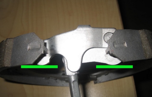
The opening in the backing plate for the cable would also have top be big enough to allow the nub on the spreader to clear.
I do like the idea of using the 944 spreader with the bell crank method already used by some.
Anyone know if real early 911 (66-68 with short wheelbase) rear parking brakes are any different than the rest? I have what I believe to be a set of 911 short rear trailing arms with brakes in my spare parts.
Great thread
Jim
Posted by: ClayPerrine Oct 7 2008, 01:26 PM
66-68 911 park brakes are the same as the later ones. The later ones just use a different center section on the backing plate for the different bearing.
Posted by: Wes V Oct 7 2008, 07:09 PM
I formally bow in humility to Clay Perrine! 
I had the local Porsche dealer pull up the PET diagram that shows the 1981 924 backing plate and I can see that modifying the 911 backing plate to work in the same fashion would be difficult and I don't think it would be worth it!!
The backing plate not only has the equivalent of the 40mm shoe support, but also the two bearing pads for the separator tabs (as shown by jcd914's diagram).
All of that could be addressed, but the little details just keep adding up to the point where it's not worth it.
(in my defence, I think it's always good to go in and "re-think" stuff that may be considered as fact)
Wes Vann
Posted by: craig downs Oct 7 2008, 11:55 PM
I've been working on this also for about two weeks. Knowing that other cars use this type of e-brake arrangement I went to Pick-a Part to look at some cars. Almost all European cars use this type of spreader.
The spreader didn't appear to be supported in the rear but relied on the notches in the shoes and spring tension from the shoes. The whole thing fit in a pocket in the backing plate that was part of the trailing arm. But one could and would be a good idea to put some support for it in the 40mm shoe anchor.
Posted by: craig downs Oct 8 2008, 12:05 AM
Here a little what I've done
You have to remove a section of the backing plate to make room for the spreader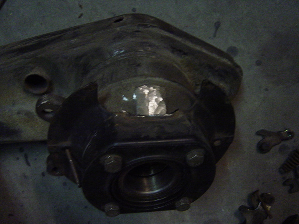
Posted by: craig downs Oct 8 2008, 12:07 AM
and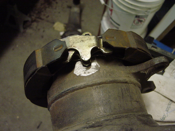
Posted by: craig downs Oct 8 2008, 12:28 AM
911 shoe on the left and a 944 on the right it the same shoe except the 944 has a notch for the spreaders instead of the pins for the 911. Also the 944 has a slot instead of a hole for the retainer spring that holds it to the backing plate.
The spreader on the left is out of a BMW which the cable pulls 90 degrees to the backing plate. The spreader on the right is from a 924/944 and the cable comes in at an angle to the backing plate.
The tangs on the back of the BMW spreader is so the loose pin that hooks the cable to the spreader doesn't fall out.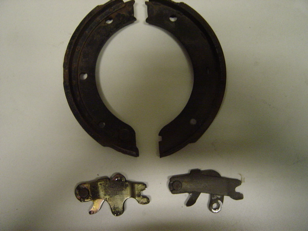
Attached image(s)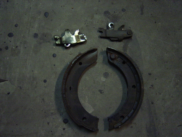
Posted by: smdubovsky Oct 8 2008, 09:39 AM
Just about every porsche other than the 911/912 & 914 uses the same newer lever design and same brake shoes 930/964/993/996/986/997/924/944/928.
Hmmm, I have some E30 parts laying around somewhere taken off the racecars. I should compare. FWIW, the E30 has a bolt on support (part #3). If its the same width as the stop plate you have to weld on anyway it could kill 2 birds w/ one stone.
Craig downs is correct. The reason for the ears is to keep the pin from falling out when you pull on the cable.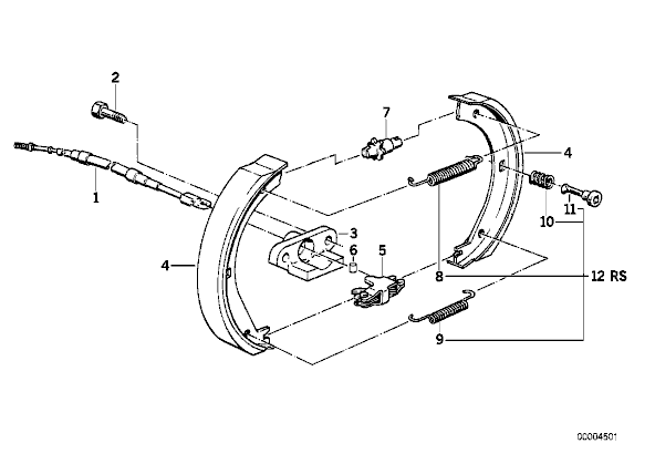
http://www.realoem.com/bmw/showparts.do?model=1113&mospid=47309&btnr=34_0330&hg=34&fg=30
Posted by: andys Oct 8 2008, 11:12 AM
Guys,
Keep up the good work. This thread is getting real interesting and informative.
Andys
Posted by: Richard Casto Oct 8 2008, 02:51 PM
Just spent a few minutes looking at PET for 924, 944 and 928 (can't get the 924S PET to download right now)
* The pad spacer is part of the 911 rear suspension arm and not the backing plate. (already knew this)
* The 76-79 924, 82-85 944 and all years of the 928 have a backing plate but the pad spacer is part of the backing plate. Hard to tell, but plate looks thicker than 911 plate.
* The 88+ 944 did not have a backing plate (or pad spacer), but rather it is part of suspension arm.
* All 928 use the same spreader (993 352 073 00) which looks to be a 90 degree pull
* All 924/944 use the same spreader (951 352 090 00) which looks to be a side pull
My take away from this is ...
* The 911 backing plate it too thin to handle loads when the e-brake is engaged. (some people weld the spacer to 911 backing plate, some weld it to the 914 rear suspension arm)
* Backing plates for the 924 and 928 were made thicker so they can incorporate the pad spacer and can cary the braking load??
* Some later cars did away with the backing plate and incorporated it into the rear axle casting.
* Backing plates between models look to be significantly different. Not sure how much if any swapping can happen.
* Would the 924/944 spreader work better as it is a side pull and that might line up better with the stock 914 e-brake setup since if I remember correctly the rear 914 e-brake is a side pull and not a 90 degree pull? Could this mean no need for a bellcrank if you use the 924/944 spreader, but just a short custom cable to bridge between the spreader and the stock 914 cable?
Posted by: Richard Casto Oct 8 2008, 02:55 PM
Craig,
Excellent job! It looks like you are well on the way of figuring this out!
I assume the next step in the photo below is to weld in a spacer for the pad and that same spacer might do the same job as the 924/944/928 backing plate and act as a brace for the spreader? After you run cables, it looks like you might have a working solution using the pull spreader!
Richard
Posted by: Richard Casto Oct 8 2008, 03:08 PM
911 shoe on the left and a 944 on the right it the same shoe except the 944 has a notch for the spreaders instead of the pins for the 911. Also the 944 has a slot instead of a hole for the retainer spring that holds it to the backing plate.
The spreader on the left is out of a BMW which the cable pulls 90 degrees to the backing plate. The spreader on the right is from a 924/944 and the cable comes in at an angle to the backing plate.
The tangs on the back of the BMW spreader is so the loose pin that hooks the cable to the spreader doesn't fall out.
Questions and comments...
It looks like you are using a 911 backing plate. With the 944 shoe having a slot vs. a hole for the retainer spring does that mean you have to use the 911 shoe? If you are using the 911 shoe, are you grinding a notch for the spreader?
Also, you mention that the 90 degree spreader is from a BMW. If you look at the PET diagram for the 928, the BMW and 928 spreader look the same if not identical.
Posted by: ClayPerrine Oct 8 2008, 03:09 PM
I have had sitting side by side in front of me a 944 backing plate and a 911 backing plate.
You have all seen the 911 backing plate.
the 944 backing plate is a cast aluminum part that incorporates both the shoe stop and the caliper mounting point, plus the bearing cap. The center of the cast aluminum part won't fit over the 914 trailing arm, it is too small. And he offset for the shoes and the caliper mount is completely wrong to work with the 914 trailing arm, even if it would fit. Plus, the caliper mount is on the back of the trailing arm on a 944, so to use it on a 914, the cable would have to come from the rear.
I like the idea of using 944 shoes and the spreader, but I will be much harder to do than the 911 setup. If someone made a custom backing plate with a cable pull from the front in parallel with the trailing arm it would be a slick item.
(DAMN... now I am thinking again!!!!)
BTW.. my park brake works fine. I drove it to work this morning.
Posted by: craig downs Oct 8 2008, 09:04 PM
I'm totally aware of how the backing plate is on a 944 and I'm not using or trying to use it I'm using a 911 backing plate. I don't understand what difference which backing plate you use. When I was looking into this idea if it would work I checked the shoe size, position, and the gap between the shoes where the spreader goes to see if they were the same as the 911 and they were. The only difference in the shoes are the pins for the 911 spreaders and the holes for the retaining springs that holds them to the backing plate. The 911 has a hole and the 924/944 has a slot.
If you want to use the 911 shoes you have to remove the pins and grind a notch for the spreaders. If you want to use the 924/944 shoes all you have to do is to drill a hole where the slots are for the spring retainers.
The shoe anchor will have rear support for the spreaders and be welded to the trailing arms.
I know your a big fan of cables which is fine. Just looking at another alternative
Posted by: Wes V Oct 9 2008, 09:31 AM
Craig;
On the prior page, jcd914 posted a photo showing in green lines where the spreader would bear on the backing plate.
The PET backing plate diagram I've seen has the spreader sitting on a raised area.
In all disk brake installations, the shoes sit on raised sections. This is true on 911 backing plates and also on 924 backing plates.
Now the question I've got (and hopefully you have a 924 backing plate you can look at) is if the raised pad supporting the spreader is at the same elevation as the pads that the shoes rest against.
Wes V
Posted by: Wes V Oct 9 2008, 12:51 PM
Craig;
Here is some more "food for thought" stuff.
If I was going to do it, this is the bracket that I'd weld to the housing.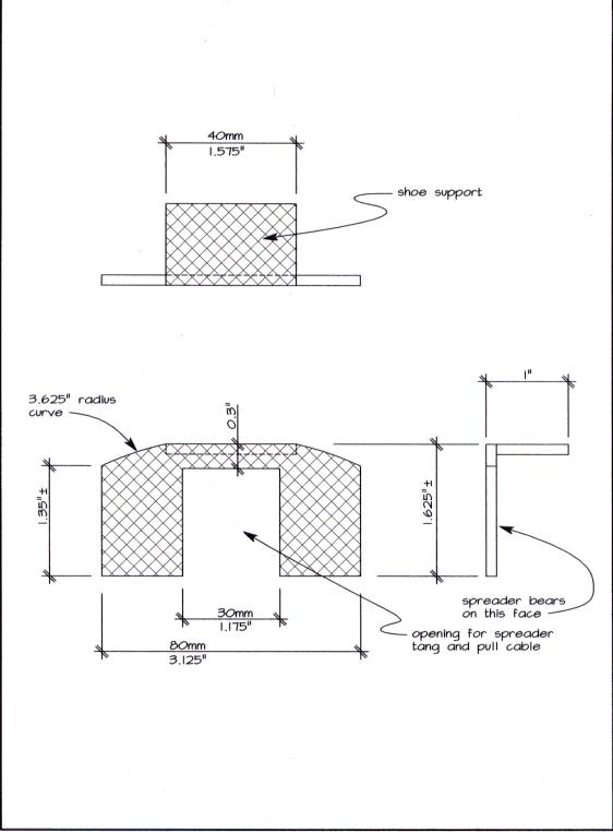
It would serve the function of having the bearing pads for the spreader and also the shoe stop.
It would be positioned where I'm holding the scale in the following photo;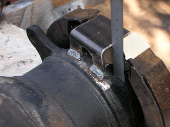
If after fabricating and installing it looked too weak (at the top), it would be possible to add a stiffener on the car side that matched the radius.
Personally, I'd just go with the 924 spreader (straight pull), but if you used the BMW one, the opening for it could be smaller. (the opening wouldn't have to clear the "tangs" on the 924 spreader, just the arm it's self.
Wes (I've got to get a life) Vann
Posted by: ClayPerrine Oct 9 2008, 02:05 PM
In the middle of the day today a stray thought about this subject crossed my mind, and in the process got stuck.
 What does the stop block everyone adds to the trailing arm actually do?
When the brake is off, the shoes rest against it.
When the brake is on, the shoes are held outward by the spreaders, and they don't touch the stop block.
So why do we need it????????? 
Posted by: Eric_Shea Oct 9 2008, 02:28 PM
Not sure if that's accurate. I believe they pivot off it.
Make a circle in front of yourself with your thumbs and forefingers. The spreader would be between your forefingers. Open the circle pivoting off your thumbs. The pivot offers stability for the shoes and prevents them from simply being ripped off by the wheel if engaged while moving.
Much needed. I believe the stop block is in the wrong position above. It should be below and the spreaders should be above.
Posted by: Eric_Shea Oct 9 2008, 02:34 PM
Wait... rethinking. You're right.
The spreader creates the pivot.
Posted by: ClayPerrine Oct 9 2008, 03:09 PM
Not sure if that's accurate. I believe they pivot off it.
Make a circle in front of yourself with your thumbs and forefingers. The spreader would be between your forefingers. Open the circle pivoting off your thumbs. The pivot offers stability for the shoes and prevents them from simply being ripped off by the wheel if engaged while moving.
Much needed. I believe the stop block is in the wrong position above. It should be below and the spreaders should be above.
I don't think the shoes pivot off the stop block. They would have to pivot off the star wheel adjuster. The stop block is on the end with the spreaders....
Posted by: ClayPerrine Oct 9 2008, 03:11 PM
Wait... rethinking. You're right.
The spreader creates the pivot.
Ok.. then what does the added stop block do??????
(I call it a stop block because I don't know what else to call it.)


Posted by: Richard Casto Oct 9 2008, 03:16 PM
I think another way to say what Eric is saying is...
While you have the pins that keep the shoes attached to the backing plate, pretty much the shoes, spreader and adjuster pretty much float. If you didn't have what we are calling the "stop block" or "spacer", if you engaged the e-brake and tried to move the car, it would either rip the pins from the backing plate or break the pins as the shoes, spreader and adjuster rotated with the disk/drum and the backing plate remained stationary. You also wouldn't rotate much before your cable broke or yanked the spreader out from between the two shoes.
So while the spreader moves them apart, most likely one or the other shoe (depending upon which way the car wants to move) is in contact with the stop block. This is why in my opinion you should not weld the stop block to the thin walled 911 backing plate. And as you mention Clay the 944 backing plate it a heavier cast part and not a thin stamped part because it includes the stop block and can take the load.
The load at rest on the level is probably pretty small/next to nothing. But I think that the load is much higher if you tried to engage the e-brake while moving or if you are parked on a hill.
Posted by: Wes V Oct 9 2008, 03:40 PM
I agree with what Richard is saying.
Think of the shoes, adjuster and spreader as an assembly that is free to float.
To play with numbers:
When you first pull on the parking brake, each shoe moves away from the block an equal 1/8". You then push the car forward, the assembly would rotate until one of the shoes came in contact with the block. Then you push the car rearward, the assembly would rotate in the other direction and the other shoe would come in contact with the block.
Using those numbers, if you rocked the car back and forth, the spreader would move 1/4".
If you yank on the parking brake while the car is in motion, one of the shoes is going to hammer into the block!!! All of the rotational force gets transfered through that small contact surface on ONE shoe!!!!!
Wes
Posted by: smdubovsky Oct 9 2008, 03:52 PM
If you yank on the parking brake while the car is in motion, one of the shoes is going to hammer into the block!!!
Wes
Richard & Wes are right. You can see the rub marks on the block on a 911 where this happens. The block on the early steel trailing arms is ~1/4" thick. IIRC, The aluminum ones are even thicker. I have both at the house and can measure tonight. This is one place you want to use something beefy.
Posted by: PRS914-6 Oct 9 2008, 03:58 PM
Guys, you have to have a firm stop and the shoes have to float. When you apply the parking brake when moving the entire shoe assembly rotates . Picture the rotating drum, the shoes go out and when contact is made the spinning drum tries to rotate the entire shoe assembly. That's why the bottom is not anchored. It's called self energizing and uses the rotation of the drum to help with the braking action. It's supposed to rotate against the stop and why the flimsy sheetmetal backing plate can not be used to stop the rotating force. That method is an accident waiting to happen. You ever wonder why car brake shoes have more material on one side than the other? It's the self energizing effect that shoves the shoe harder against the drum and the driven shoe gets more material to compensate.
If you anchored top and bottom it wouldn't work worth a crap.
Posted by: Eric_Shea Oct 9 2008, 06:49 PM
I almost had it 
The "stop" prevents the shoes from being ripped off the entire assembly.
That problem seems solved.
Posted by: craig downs Oct 10 2008, 12:53 AM
Lots of good information this is a fun thread and totally different what Wes has started
I hope you don't mine about your thread being hijacked.
I was going to use the one from the BMW and use a bell crank to operate it until
Richard Casto brought up about using the 924/944 spreader and hooking up direct.
So today I explored this a I think its going to work as there will be no bell crank to make.
Clay brought up an interesting point about the shoe stop. I checked to see if the shoes could be twisted back and forth and they could plus you can see a shiny area where the shoes would make contact with the stop.
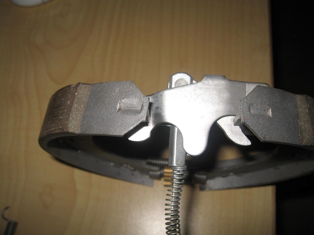
Here is what I found out today as I tried the 924/944 spreader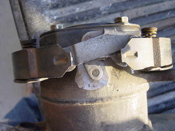
Posted by: craig downs Oct 10 2008, 01:00 AM
Checking cable line up. Going to cut and realign cable mount and make a rod extension to reach the spreader.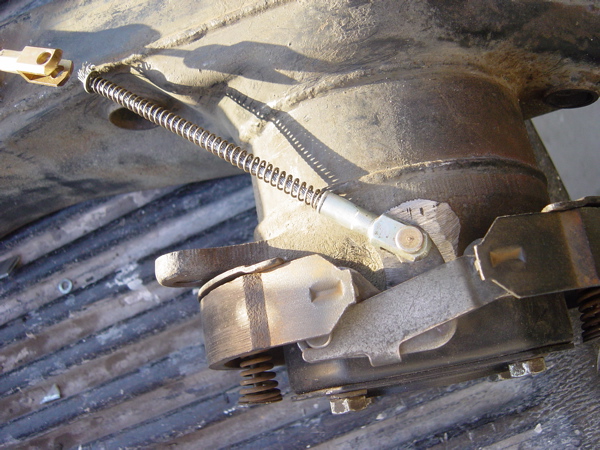
Posted by: craig downs Oct 10 2008, 01:09 AM
In the relaxed position 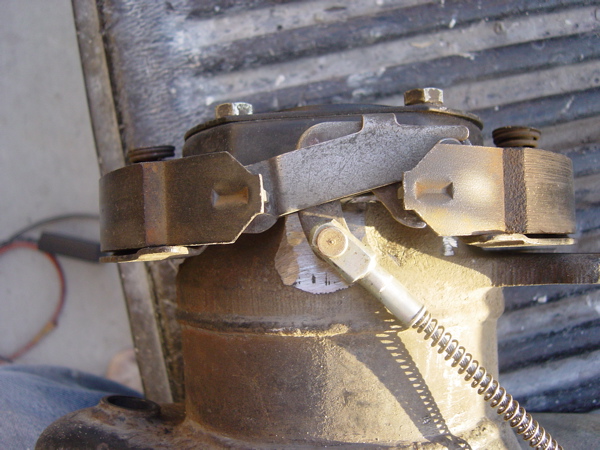
In the pulled position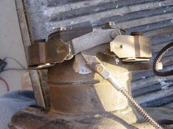
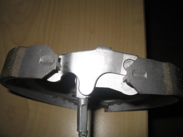
Posted by: craig downs Oct 10 2008, 01:17 AM
Mocking up a shoe stop I'll make them up this weekend. The stop will have to have support blocks welded on to reach the rear of the spreaders.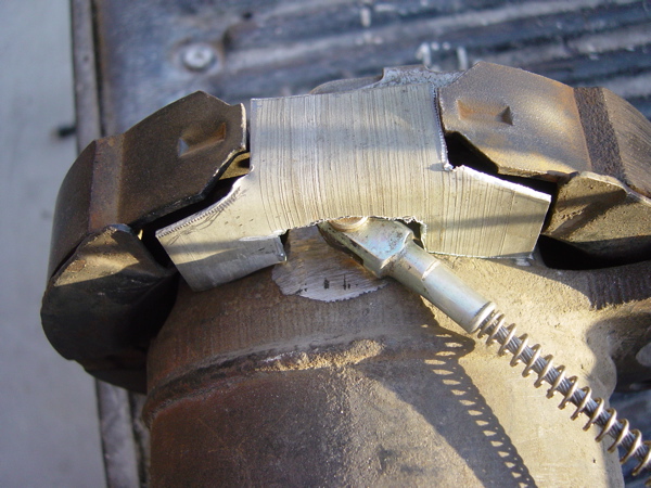
Posted by: craig downs Oct 10 2008, 01:22 AM
This show why the spreaders need rear support as you see the shiny spots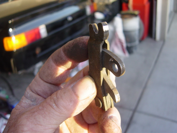
Posted by: Wes V Oct 10 2008, 09:02 AM
Lots of good information this is a fun thread and totally different what Wes has started
I hope you don't mine about your thread being hijacked.
I have NO problem with how this string has morphed!! (I originally just wanted to brag about finding that VW bus cable)
There has been a lot of good information covered and ideas explored. I like the idea of it being in one area!
I like what Craig is doing, however I think using a hard connection between the spreader and 914 cable would be easier to do than a cable. Think high strength threaded rod (from McMaster Carr) and clevis's.
Am I correct that there is a "left" and a "right" version of the BMW spreader? It would seem that there would have to be in order to have the angle of pull match the side it's mounted on.
Wes
Posted by: Wes V Oct 10 2008, 09:23 AM
Craig;
Here is an idea for you to think about;
Make up a clevis with a female m6x1.0 thread (I think that's the thread size, I'll check), then use that longer VW bus cable. It screws into the clevis and has a jam nut. By doing that, you would have a continuous cable (with about 18" exposed between the 914 sheathing bracket and the clevis).
The bracket for the 914 cable sheathing would have to be re-located and pointed in the correct direction. Which you will have to do anyway.
You would still have to make a cable end at the firewall area, but that's been covered.
Wes Vann
Posted by: Wes V Oct 10 2008, 09:50 AM
The stop will have to have support blocks welded on to reach the rear of the spreaders.
This comment has me confused!!
As I read it, you are saying that there is a "stop" that limits how far to the side the spreader can move. (in addition to rubbing on the "backing plate")
I can't see the need due to the fact that the shoe will only move outward a certain amount and that would limit the side to side movement.
(as you pull on the cable, it would pull the spreader and shoe assembly off to that side and stop once that shoe is in contact with the drum. Then continuing to pull would spread the other shoe outward)
It may have somthing to do with the fact that there will always be a certain amount of tension on the cable??
Maybe I'm just reading your comment wrong!!!
If you could add an arrow to the photo showing the wear pattern on the spreader, it may make it clear.
That brings up another subject!
Are you planning on installing a "return" spring (as shown on that sub-cable)? I haven't seen anybody show consern about it, even in bell-crank versions.
In most versions, everybody is counting on the shoe return spring (the one near the spreader) on pulling the cable back!!!!!
In the original 911, there isn't an additional return spring, but that's a straight pull.
What was there in the original BMW installation?? (wish I had a black E30 to look under!)
Wes
Posted by: Phoenix-MN Oct 10 2008, 09:57 AM
"Are you planning on installing a "return" spring (as shown on that sub-cable)? I haven't seen anybody show consern about it, even in bell-crank versions.
In most versions, everybody is counting on the shoe return spring (the one near the spreader) on pulling the cable back!!!!! "
A spring like this? It pushes the spreader back when tension is released off the cable.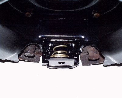
Paul
Posted by: Richard Casto Oct 10 2008, 12:47 PM
The stop will have to have support blocks welded on to reach the rear of the spreaders.
This comment has me confused!!
Wes, you are a good sport for allowing the thread hijack.
 And Craig stop me if I am way off base here.
So, I "think" that what Craig is saying when he says the "rear of the spreaders" is the part that would be next to the backing plate. And that in addition to pushing against the shoes, the spreaders also need to push against something along the other axis to prevent from putting an un-needed side load on the shoes.
The image below is without a plate for the spreader to push against. The green arrow is the force from the cable. The red arrows is the force from the spreader on the shoes. So you see in addition to the force that pushes the shoes against the drum, you also have an un-needed side force.
In the image below, the blue is a plate for the spreader to push against. The green arrow is the force from the cable. The red arrows is the force from the spreader on the shoes. The purple arrows is the force from the spreader on the blue plate. So here the only force on the shoes is the ones pushing them against the drum.
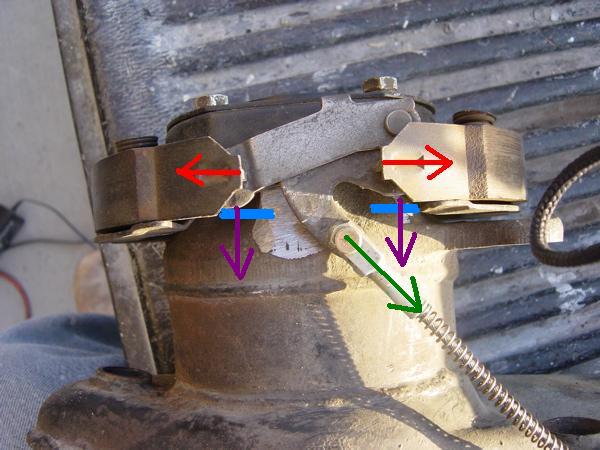
Also in the above photos you can see how the two pivot points on the spreader are offset away from what would be the backing plate. So if I understand Craig correctly, I think he is saying that in addition to just bending a flat section of metal 90 degree to create the “stopping block” that he may also need to weld in something extra (what I show in blue above) onto that to take into account that offset.
In the image below, you can see the bent "stopping block" but with two extra sections welded on to account for the offset and meet up with the spreader.
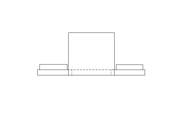
Posted by: Richard Casto Oct 10 2008, 12:50 PM
Mocking up a shoe stop I'll make them up this weekend. The stop will have to have support blocks welded on to reach the rear of the spreaders.
Looking at this image again and since I don't have the parts in hand, only Craig can answer this, but he may be sneaking his 90 degree bend section under the shoe a bit so that the two extra bits I just mentioned above may not be needed. That means the spreader might be able to rest directly on the part he has roughed out above.
Posted by: Richard Casto Oct 10 2008, 01:01 PM
Continuing to think out loud here. I promise this is my last post for awhile.
Here is the backing plate for a 924 (image from PET)...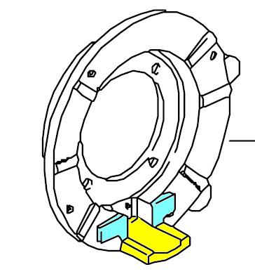
The yellow is what we are calling the "stopping block". On the 911, this is not part of the backing plate, but rather part of the arm. You can see how thick this casting is on the 924 vs the thin 911 stamping. The blue section that rises up higher than the surrounding area, is what I think the spreader pushes against. I think it rises up to account for the offset seen in the photos above. This might be what Craig is calling "support blocks" in his post above.
Craig and others, what do you think??
Posted by: Wes V Oct 10 2008, 01:27 PM
Richard;
I think your "drawn" diagram is what Craig is talking about when he says he has to weld on something additional. (that's the only thing that makes sense)
As you said, if the L shaped bracket is within the shoes, then it can be positioned such that added blocks wouldn't be required.
Wes
Posted by: smdubovsky Oct 10 2008, 04:05 PM
Heres a pic of an early steel 911 arm. The late aluminum arm is slightly thicker (didn't get a good photo on that one.) FWIW, the bracket is 39-40mm wide on both of them. I got to thinking - the tab is probably thick to account for shoe & rotor wear. The worst case limits are a new shoe on a new rotor (smallest ID) and worn shoes on worn rotors (largest ID). You don't want the lip of the shoe to slip over the block. That would wedge it in and lock the wheel in a big way.
I think there needs to be some sort of return spring. The little lever has a very high ratio. Cable drag could easily cause it to not fully release.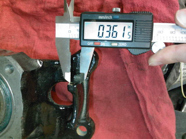
Posted by: craig downs Oct 10 2008, 07:04 PM
Richard figured it out what I was trying to explain about the rear supports. In his diagram the spreaders need back support where he has the blue lines.
As far as the spring goes I was planning on having a coil spring over the cable that goes from the cable housing to the top of the cable like the one I have pictured. All the cars I looked at they had a return spring around the cable.
Posted by: Steve Jan 3 2009, 12:23 PM
I would love to do this to my car. Does anyone know of a shop or someone that can weld up the required brackets on my trailing arms in Southern Cal? I do not own a welder and haven't welded anything since high school 30 years ago.
Thanks!!
Posted by: burton73 Jan 3 2009, 06:36 PM
Steve,
You are still going to need a set of rear p-Brakes. I paid $150. With the cables from Easy. Someone had a set with cables on the Pelican board for $175. Past that you can clean them up and paint them and them figure how to put them on. That is where I am. There are a few different ways to do it as shown by our members.
Bob
Posted by: charliew Jan 4 2009, 05:27 PM
It looks to me that the aluminum arm style straight pull 911 spreader arm could be modified to be like the 944 spreader arm in a pinch and also if the leverage ratio needed to be changed, it could be done along with a different pull rod fastener if needed. ie a different size hole or etc.
Thats a great find on the angle spreader.
Posted by: Steve Jan 4 2009, 07:57 PM
Steve,
You are still going to need a set of rear p-Brakes. I paid $150. With the cables from Easy. Someone had a set with cables on the Pelican board for $175. Past that you can clean them up and paint them and them figure how to put them on. That is where I am. There are a few different ways to do it as shown by our members.
Bob
Thanks Bob!! I pm'd the guy on Pelican but I haven't heard back from him. I will call some wrecking yards tomorrow and see what I can find.
Posted by: charliew Jan 5 2009, 11:34 AM
I bought some 911 rear brakes and aluminum arms on samba and ebay. You probably need to know which years you want though. The two sets I have I think are 74 911 and 84+ maybe 944?, thats what I marked on them when they were sold to me. The 74 are straight pull and the 84 are angle pull. The straight pull come out the cavity for the stub axle and the angle pull comes out a angled port in the aluminum arm. The later arms are for a wider wheel. It seems from what everybody has contributed that the deal is to use the 911 backing plate with the notched brake shoes and the 944 spreader or the straight spreader and a neat two piece bellcrank like the one already designed. It won't be long and this could be a kit for the guys that don't fab.
On looking back at wes's thread on the cable/backing plate install, which is GREAT I wonder if you could just use the inner 1/2 of the original 911 rivet style spreader and make it pull only with a simple bellcrank and a rod to the bellcrank and a rod to the stock 914 cable? That way the replacement parts would mostly be early all 911. It sorta looks like the backing plate could be rotated 180 and put the cable and spreader on top maybe not.
I found this on the net. The spreader might be called a expanding lock, they also have a support and shoes but I will probably just have mine relined. http://www.bavauto.com/se1.asp?dept_id=168 The angled spreader is called a expanding lock, it's part # 34411163709 it's down the parts list aways.
I just called Larry at 20th st in AZ. and told him I wanted early 911 backing plates off of the steel arms and 84 944 expanding lock's and adjusters and even shoes if he has them and he said he didn't have any 924 rear brake parts at the moment but he will call me when he gets them. A guestimate was very reasonable. http://www.20thstreetauto.com/porsche/porscheparts.htm#924
He seemed to have a knowledge of the application we are working on. Seems like a good place to get the small stuff so I won't need to rob the complete arms I have.
Added 01/06/09
Ok the guys at 20th st called back. Larry and Mathew. I got early 911 (68?) backing plates off of steel arms, 84/944 shoes, and all attaching hardware with the angled expanders for 140.00 + shipping. That is a little expensive for some but porsches are a little hard to come by in Crawford. At least the part chasing is done for this deal. If you mention my name they know what you are doing. Charlie Wittmer
01/07/09 found another good place to get the parts, it's planetporsche the guys name is Bill Martin They have lots of porsche stuff I originally found them on ebay He had some new shoes and a good 944 cable that I may use with a 944 brake handle. I kinda want the emer.handle in the center.
It looks like with a little imagination a bolt on support could be fabbed up and the support could be a drill and tap the arm and mount the support deal for the ones that don't fab.
Posted by: Steve Feb 21 2009, 11:13 PM
I bought these parts from Parts Heaven. They do not look right but there is no part number on the brake shoes. Are these the correct brake shoes? As you can see in the picture the holes do not line up and they are hitting the brake shield bolt hole.
Attached thumbnail(s)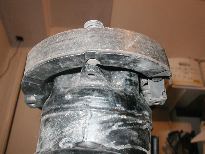
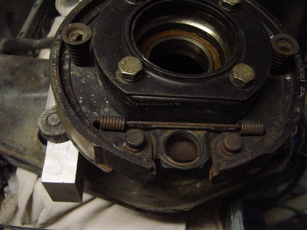
Posted by: Steve Feb 21 2009, 11:14 PM
Here's the one with the bolt holes.
Attached thumbnail(s)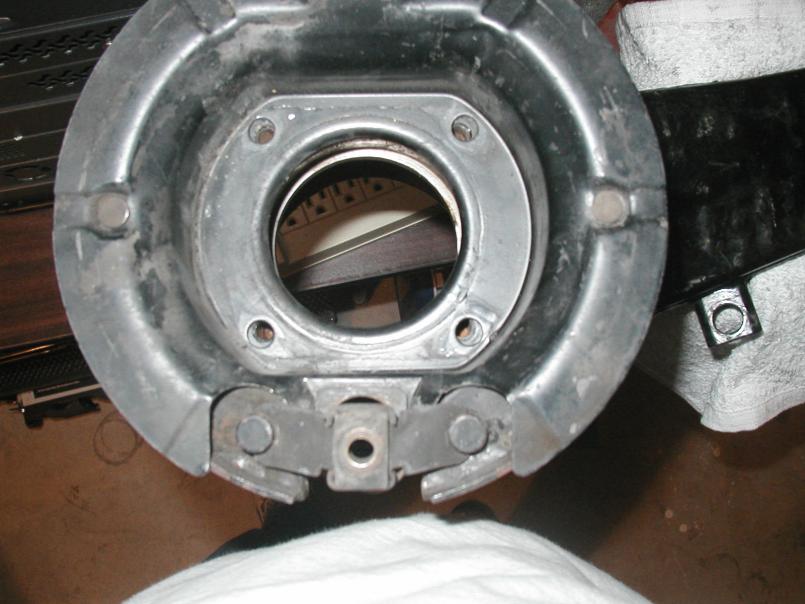
Posted by: craig downs Feb 22 2009, 01:42 AM
You happen to get a later year e-bake assembly that had the trailing arms with a wider bolt spread. All you have to do is file or grind the bolt hole to match your trailing arms. I got the same one as you have and had to do this. As far as the brake shield tab goes you have to cut them off.
Posted by: jaxdream Feb 22 2009, 11:34 AM
Hi guys , I too have been wanting a 911 ebrake setup similar to what is going on here .I have been studing all the threads on the forum and figured that there was a "different " way to do e-brakes , Craig is on the same path that I come up with including the little box that the spreader works in and rchard is right about the raised portion of the backing part of the box. This setup will work on the angled pull similar to tha 924 , taking the 90 bend out of the eqation and moving the cables closer to the arm for protection, I haven't posted any of my workings yet as they are in my parts colection , but have spent a few hours studing the parts and their operations , personnaly this IS the most effective setup I've seen yet and should prove to be an asset to guys wanting a reliable e-brake setup . I got most all of the parts mention here off of the e-place , was just patient and got most for very cheap , 928 rear hubs spindles e-brake,shoes spreaders , partial cables $50 something delivered!! Isee welding an shoe stop to the arm similar to the E-30 part with a tube perhaps that would give the angle of the 924 , either with cable if possible or a rod of sorts , but like Craig has mentioned it has to have the springs on it for return of the spreader . I like this thread !!!!!!! 
Jaxdream
Posted by: PRS914-6 Feb 22 2009, 12:06 PM
Actually, if you have good cables the two springs in the backing plate assembly and the one in the cab are plenty to easily retract the shoes and cables. However it would not be difficult to install a coil spring over the cable like most American cars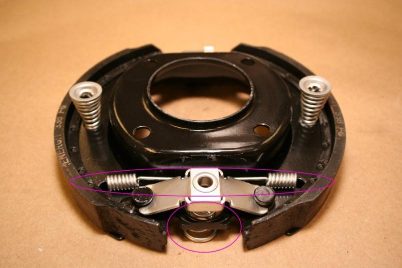
Posted by: scotty b Feb 22 2009, 12:19 PM
I think I still have a complete 86 944 rear suspension if you guys want/need any pics of the original configuration. Not sure if at this point ti would help or not
Posted by: charliew Feb 22 2009, 01:24 PM
The later angle pull spreaders are to me the best solution. You can grind the little notches in the early shoes if thats what you have. You might need to remove the center pull or push studs off of the early shoes though.
Posted by: Steve Feb 23 2009, 09:03 AM
You happen to get a later year e-bake assembly that had the trailing arms with a wider bolt spread. All you have to do is file or grind the bolt hole to match your trailing arms. I got the same one as you have and had to do this. As far as the brake shield tab goes you have to cut them off.
Thanks Craig for the reasurance. I just wanted to make sure before I start grinding away at the thing.
-Steve
Posted by: Steve Jul 29 2009, 06:40 PM
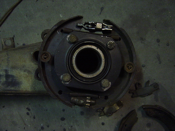
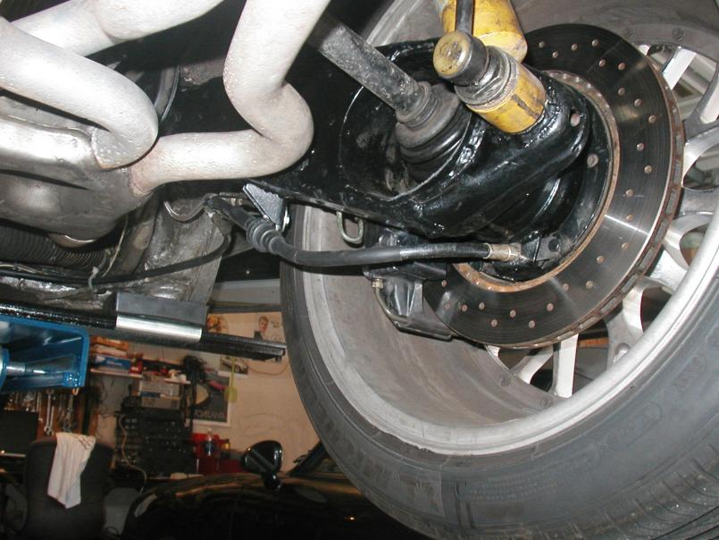 I finally put mine together and tested it out at Willow Springs short track. I am running Boxster rear brakes and 944 turbo front brakes. I ended up copying pretty much everyone. Thanks again to Wes for welding up the stop plates on my trailing arm. For the least amount of hassle I ended up using 914 clutch cables, cut to length and stock 914 emergency brake outer sheathing.
Posted by: Steve Jul 29 2009, 06:45 PM
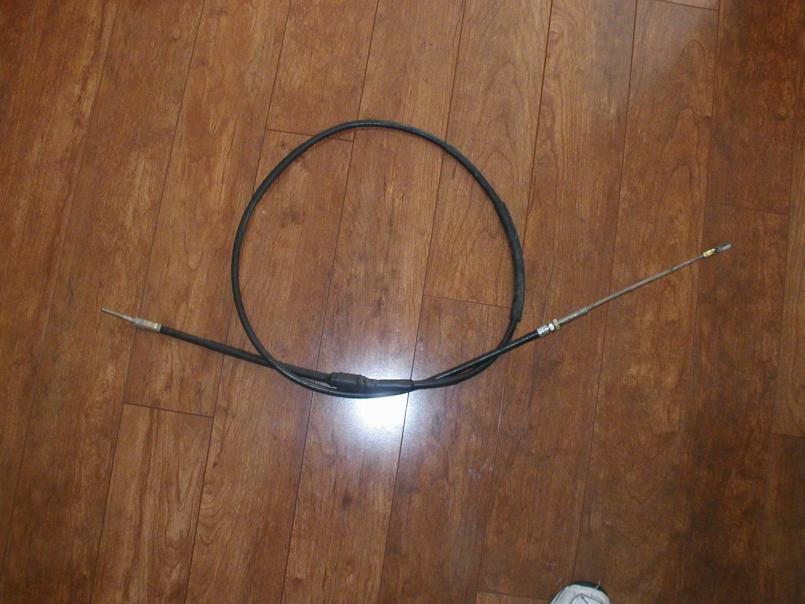 Here's a picture of the fabbed up cable. You can see in the picture that i used the stock 914 outer sheathing and a piece of the 914 clutch cable outer sheathing. I used a 2" piece of 5/8th OD copper pipe to tie them together. I notched the copper pipe to support the stock C clip on the 914 E. brake cable. I pretty much copied Clay, but used a piece of the clutch cable sheath versus bending a piece of conduit. Pro's and con's on all the techniques, but mine was the least amount of hassle for me and my lack of welding and fabrication skills!!
Posted by: Steve Jul 29 2009, 07:14 PM
Here's another picture of the copper pipe before I covered it with shrink wrap.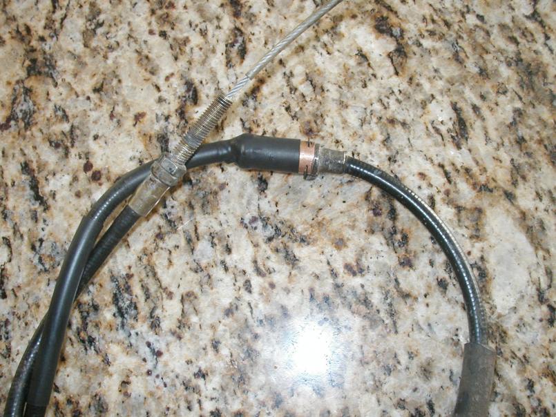
Powered by Invision Power Board (http://www.invisionboard.com)
© Invision Power Services (http://www.invisionpower.com)