Printable Version of Topic
Click here to view this topic in its original format
914World.com _ 914World Garage _ Interesting find
Posted by: MrKona Feb 14 2009, 10:05 PM
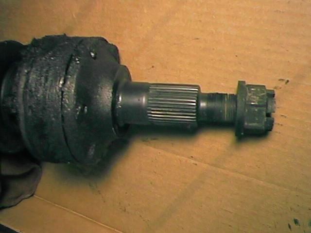
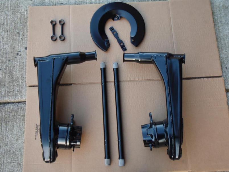
I bought a five lug set up today from a local guy off craigslist. The front is a Boge set up with 3" spacing and M-calipers. I already have a pair so I will most likely be selling these off in the near future.
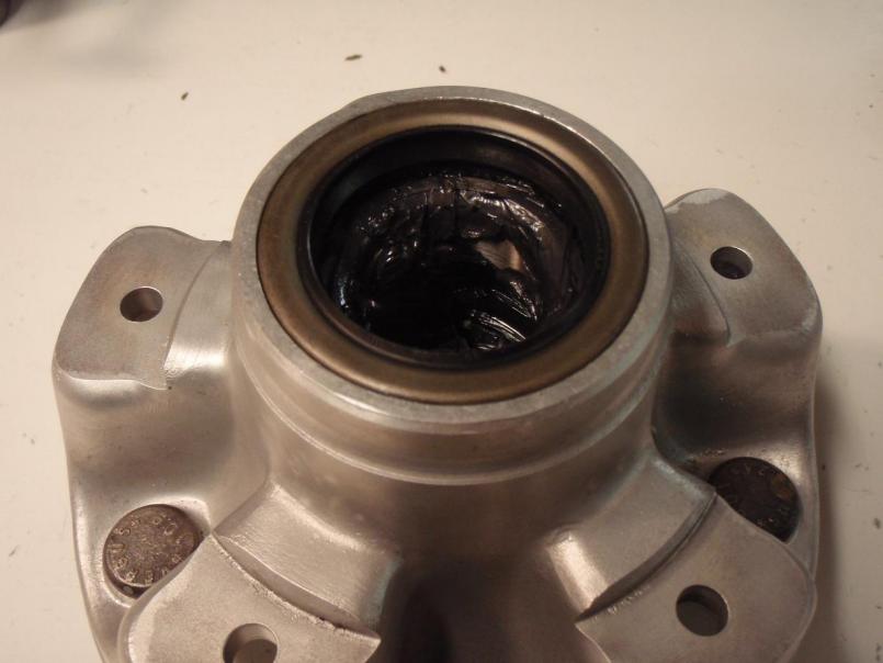
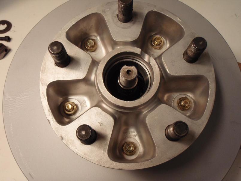
It's the rears that got my attention. The hubs are originally five lug, not four lug redrilled for five. The guy who sold them to me took them off a 914 he parted out a long time ago and has been storing them ever since for an eventual five lug conversion. He sold them as he has too many projects as is.
Unfortunately, I'm going to be gone for a few days and won't get a chance to dig into these until next weekend. I'm wondering if I may have acquired a set up with 914/6 stub axles. 
By the way, anyone have a suggestion on how to remove the big castle nut with the suspension off the car? 
Attached thumbnail(s)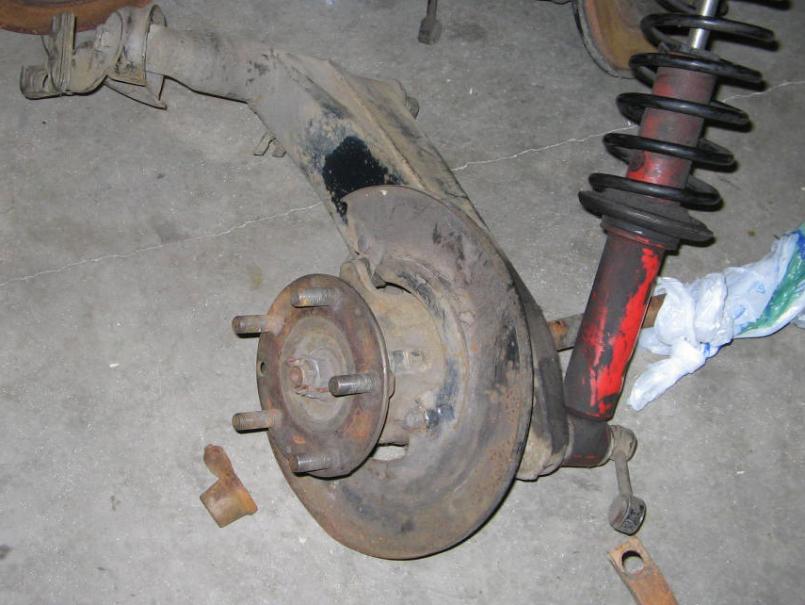
Posted by: MrKona Feb 14 2009, 10:06 PM
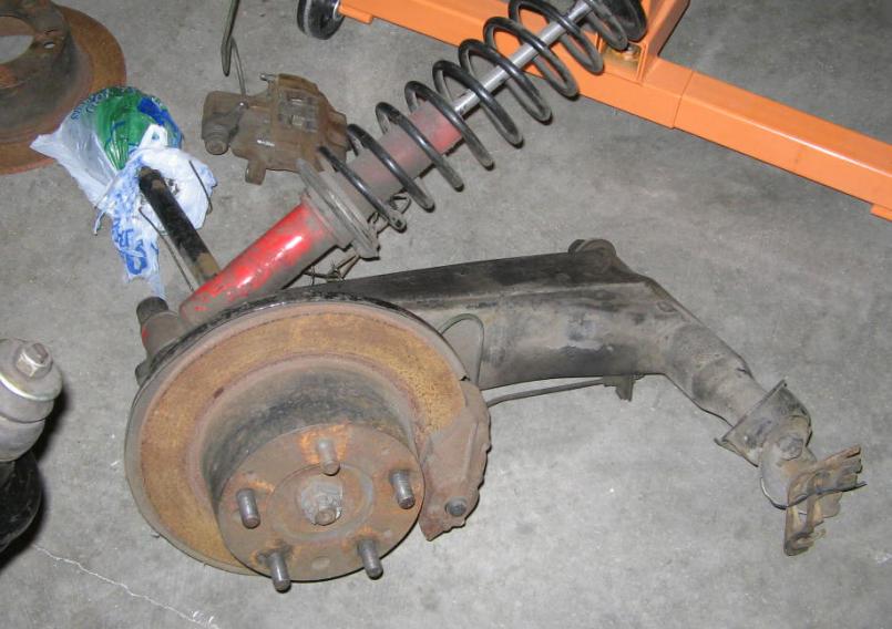
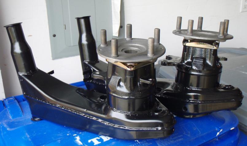
Front...
Attached thumbnail(s)
Posted by: boxstr Feb 14 2009, 10:33 PM
Let me guess, the guy lives in Columbia City, out by St Helens.
I emailed him last night and asked how much he wanted$$. He replied $300.
I said I will take them. He replied Okay they are yours.
He says he can deliver to OC on way to work. Okay, sounds good.
Then I get an email today that the five lug is gone, for $500.
I guess money talks.
Posted by: MrKona Feb 14 2009, 10:41 PM

Let me guess, the guy lives in Columbia City, out by St Helens.
I emailed him last night and asked how much he wanted$$. He replied $300.
I said I will take them. He replied Okay they are yours.
He says he can deliver to OC on way to work. Okay, sounds good.
Then I get an email today that the five lug is gone, for $500.
I guess money talks.
Yah... I made him an offer today (actually less than $500) and he took it. Sorry Craig... didn't know...
Posted by: boxstr Feb 14 2009, 10:50 PM
Yeah, No blame to you. You didn't know.
Posted by: my928s4 Feb 14 2009, 11:05 PM
By the way, anyone have a suggestion on how to remove the big castle nut with the suspension off the car?
A decent impact wrench worked for me.
Posted by: Todd Enlund Feb 14 2009, 11:14 PM
Man, I was way too slow...
So, Bryan... your other struts are 3" as well? I've got a pair of "A" calipers/hubs/rotors, and need some 3.5" struts.
Posted by: MrKona Feb 14 2009, 11:24 PM
By the way, anyone have a suggestion on how to remove the big castle nut with the suspension off the car?
A decent impact wrench worked for me.
Yup, I'll use an impact wrench on them, but with no car on the other end of the axle, what do I use to keep the axle from turning? My wife recommended I find a couple of strong men to hold it.

Posted by: MrKona Feb 14 2009, 11:26 PM
Man, I was way too slow...
So, Bryan... your other struts are 3" as well? I've got a pair of "A" calipers/hubs/rotors, and need some 3.5" struts.
3.0" struts only here, no 3.5"... I'm sure there is a set of 3.5" struts out there with your name on them...
Posted by: LarryR Feb 15 2009, 12:47 AM
My experience was that I was lifting the entire back end of the car off the ground to break those bastards loose. I would take a torch and heat them up a lot then hit them with the impact to bust them loose. a couple days soaking of liquid wrench could help too.
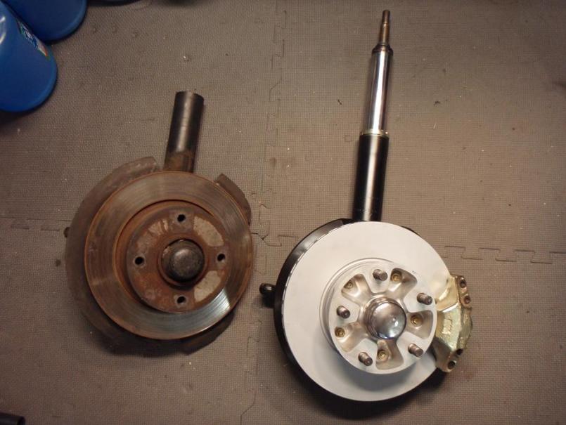
As for being factory six all you have to do is look at the solid rotor to realize that is not the case. However, I am confused as to why they are 5 lug calipers (non vented) but have no extra holes on the rotors. (early 911 rotors working with the 914 hubs?)
great buy.
Posted by: Todd Enlund Feb 15 2009, 12:49 AM
3.0" struts only here, no 3.5"... I'm sure there is a set of 3.5" struts out there with your name on them...
I'm sure there is... I'll look harder when I have more money
Looks like you scored big on this setup.
Posted by: McMark Feb 15 2009, 01:28 AM
914/6 had solid rotors in the rear. What's the price on those 3" front struts? PM me.
Posted by: kwales Feb 15 2009, 09:37 AM
Dremel and hammer and chisel, buy a new nut.
Ken
Posted by: Eric_Shea Feb 15 2009, 10:22 AM
Couple of things:
Nut = Acetylene cherry red and then have a go at it. You may want to use that one solid rotor we see in the picture and, by first removing the backing plate, put it in a vise. You'll have to crank down on it but, if you can get that nut hot enough it will probably spin. All this depends on the proper air wrench as well. They're not created equal.
What is it? = I'd check the front end first for clues. The spline count will probably be 911 for sure however, check the torsion bar thickness. You may have the 17mm 914-6 bars. That would be a clue.
Rears would be easy enough to tell. Hubs should have a 901 part number on them. CV's would be 914 sized CV's. Real -6 stub axles have a cast finish on them. Search a thread by Reid on the subject (Lavanaut) from last month.
The left rear arm would have an extra tab for the heater flapper cable. This is just a simple tab maybe 1" wide by 1.5" tall with a single small sheet metal screw hole in it that a vinyl/cloth strap was looped through to hold that cable on 6's. Bear in mind, these control arms were used on all early 914's so it's nothing unique however, with 901.xxx.xxx.xx hubs, factory stub axles and this tab, you probably have a set off a six...
...now; where that car he stripped? 
Posted by: sixnotfour Feb 15 2009, 10:27 AM
The caliper in the background is a -4 caliper.
Whats the spline count on the axles?
The front hub looks to be hubcentric which would be later.
Posted by: 736conver Feb 15 2009, 11:38 AM
If you cant get em off, you can always ask your local wrench to remove them.
Hey Craig cant get all the deals.
Posted by: MrKona Feb 15 2009, 01:47 PM
I had to spend some today to see what I've got... I took Eric's advice with the disk-in-the-vice technique and heat. My impact wrench loosened the axle nut without too much trouble. I was pretty surprised.
I tapped the stub axle and out came.... what I believe is a 914/6 stub axle! 28 splines, sure looks like one, but I've only seen them in pictures! Can anyone confirm?
Attached thumbnail(s)
Posted by: MrKona Feb 15 2009, 01:48 PM
Another..
Attached thumbnail(s)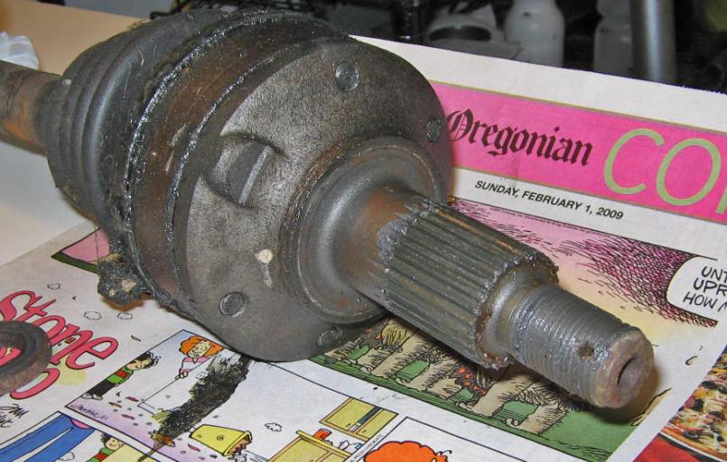
Posted by: MrKona Feb 15 2009, 02:15 PM
On the front, I measured the torsion bar diameter at 18.0mm with 29 splines. I believe this matches up to a stock 914/4 (stock diameter 17.9mm) bar.
Posted by: my928s4 Feb 15 2009, 03:18 PM
I had to spend some today to see what I've got... I took Eric's advice with the disk-in-the-vice technique and heat. My impact wrench loosened the axle nut without too much trouble. I was pretty surprised.
I tapped the stub axle and out came.... what I believe is a 914/6 stub axle! 28 splines, sure looks like one, but I've only seen them in pictures! Can anyone confirm?
Once I got a hold of a decent impact wrench I just held the drive shaft by hand and the nut came off, sounds like you had similar luck.
If you have a 914/6 rear end, sweet find for sure.
Posted by: rhodyguy Feb 15 2009, 04:53 PM
nice score.
you should have known better craig. what are ya? NEW!!? i'll be surpised if the other parts will be avail.
k
Posted by: Eric_Shea Feb 15 2009, 05:05 PM
Something on those stub axles doesn't look factory. The nubs to be more specific. I could be wrong...
Posted by: sixnotfour Feb 15 2009, 05:52 PM
could they be 108 ?
this more interesting than the Dationa 500
Posted by: zig-n-zag Feb 15 2009, 06:56 PM
The mittlemotor stubs I sold, seemed to have a thicker flange where it
mates with the cv joint, that was my impression of them.
They also could be 911 pieces added to the trailing arms, if not real /6.
Well bought!
Posted by: MrKona Feb 15 2009, 09:07 PM
Something on those stub axles doesn't look factory. The nubs to be more specific. I could be wrong...
Perhaps this solves one of the greatest Porsche mysteries ever... what really happened to the special pair of prototype stub axles meant for Ferdinand Porsche's 914-8. 38 years later, it is a mystery no more...
There are no markings on them. I haven't yet taken them off the CVs, won't be able to do that until next weekend. I'm using a picture of 914/6 stubs from Pelican parts (attached) for comparison.
Attached thumbnail(s)

Attached image(s)
Posted by: Eric_Shea Feb 15 2009, 10:41 PM
Here's a picture Andy posted in Reid's thread: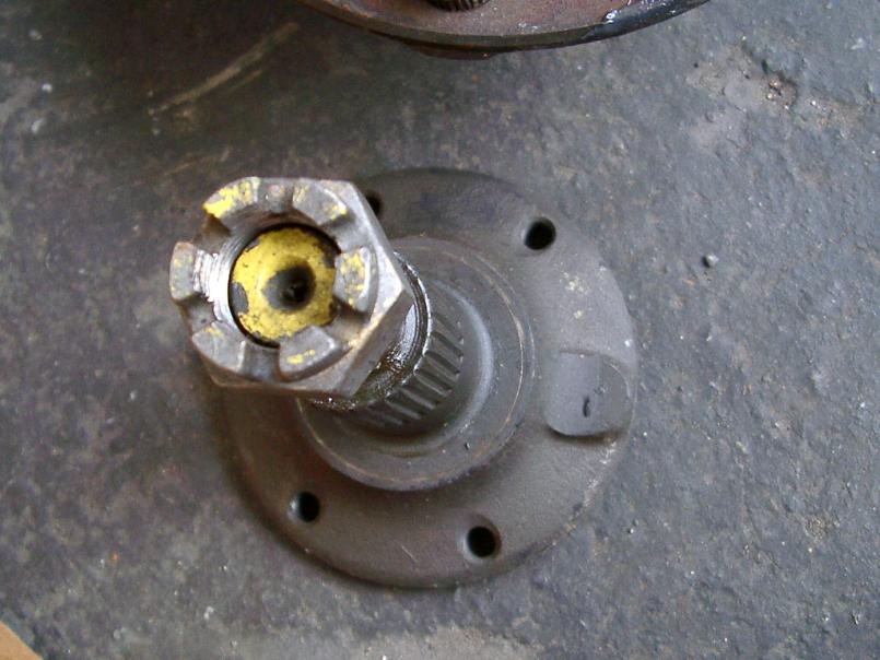
Looks like they could be the real deal.
Posted by: JRust Feb 16 2009, 12:34 AM
Excellent! Nice find Bryan 
I wonder on the set as I bought & sold a 75 I think years ago. It had a complete 5-lug setup on it. I wonder if you could special order one that way. The car was pretty unimpressive besides. I wouldn't have thought someone made the swap . I know the car made the rounds as I sold it to Craig who later sold it to someone up in Portland. Guy told me they were real 6 rears on it? Car was a 75 though? One o fthe cars I sold I should have hung onto 
Posted by: Eric_Shea Feb 16 2009, 09:57 AM
Not that I know of.
Posted by: Lavanaut Feb 16 2009, 12:35 PM
I tapped the stub axle and out came.... what I believe is a 914/6 stub axle! 28 splines, sure looks like one, but I've only seen them in pictures! Can anyone confirm?
28 splines, yep, you're golden! Nice find. Looks like those things have taken some abuse, I wonder if this is cause for concern? "I" wonder, others here will just know.
Posted by: MrKona Feb 21 2009, 12:18 AM
I tapped the stub axle and out came.... what I believe is a 914/6 stub axle! 28 splines, sure looks like one, but I've only seen them in pictures! Can anyone confirm?
28 splines, yep, you're golden! Nice find. Looks like those things have taken some abuse, I wonder if this is cause for concern? "I" wonder, others here will just know.
I don't think so... the grooves are equal on both stubs and and look like they're "supposed" to be there. Strange though, as they are absent in the pictures of other 914/6 stubs... I noticed that too...
Posted by: MrKona Feb 21 2009, 12:22 AM
I've begun to disassemble the rear trailing arms. I drove out the hubs with a metal pipe and hammer, and then removed the stubs from the CVs. I had to figure out how to hold the axles to loosen the CV bolts with the axles removed from the car. I ended up bolting the already removed hubs to the disks, then clamping the disks in a vice, then fitting the stub inside the hub, which worked just fine.
All I can say is what a dirty, greasy, disgusting mess this is.
Attached thumbnail(s)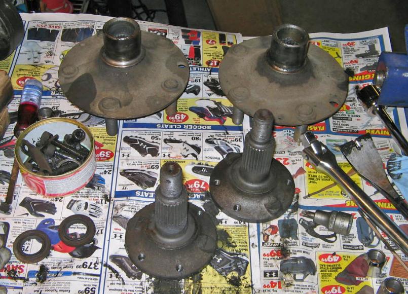
Posted by: MrKona Feb 21 2009, 12:24 AM
Tonight I removed the bearings from the trailing arms. In order to do this atraumatically, I made a homemade bearing puller for about $10 and a trip to Ace Hardware.
Attached thumbnail(s)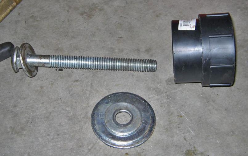
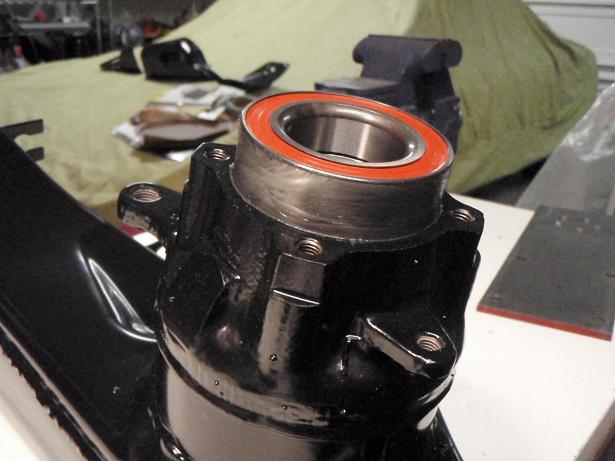
Posted by: MrKona Feb 21 2009, 12:26 AM
Bearing cap and removal... Did I mention what a dirty mess this is?
Attached thumbnail(s)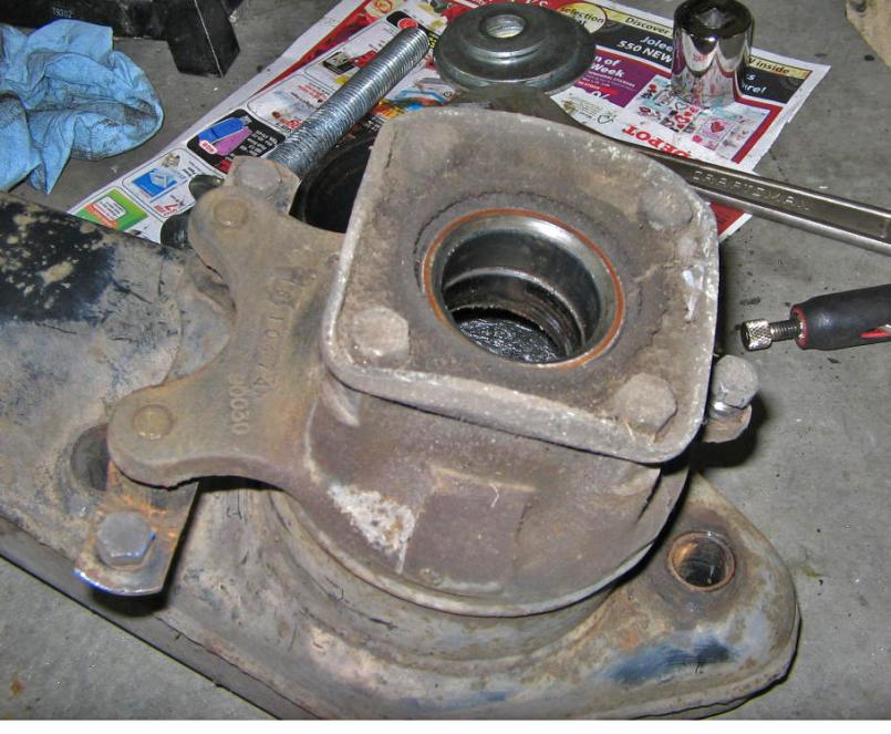
Posted by: MrKona Feb 21 2009, 12:27 AM
Bearing cap removed..
Attached thumbnail(s)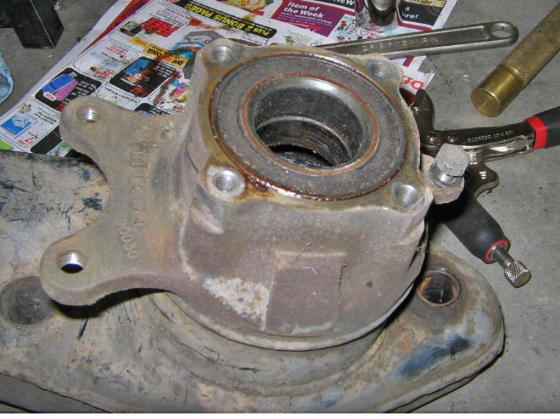
Posted by: MrKona Feb 21 2009, 12:28 AM
My homemade tool in action!
Attached image(s)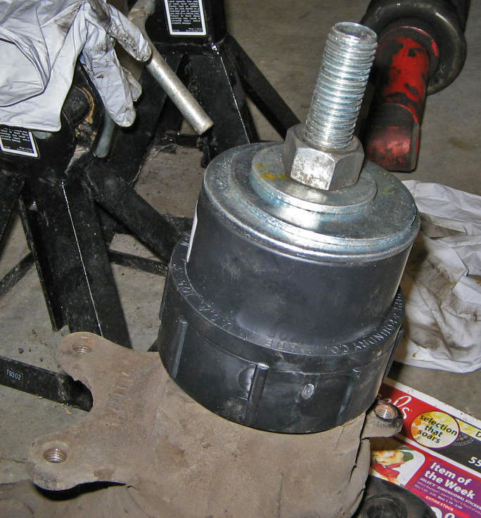
Posted by: MrKona Feb 21 2009, 12:30 AM
And the result! Held the big bolt with a Vice Grip, turned the nut, and the bearing came out like buttah!
Attached thumbnail(s)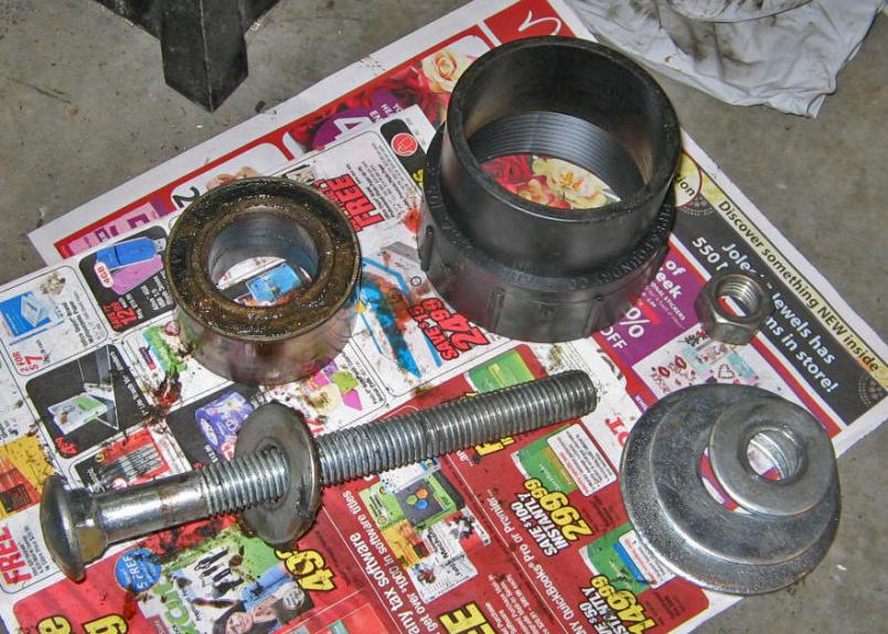
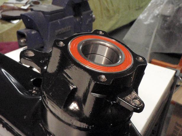
Posted by: MrKona Feb 21 2009, 12:31 AM
Bearing removed...
Attached thumbnail(s)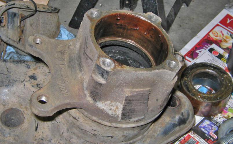
Posted by: MrKona Feb 21 2009, 12:36 AM
Question... the inside of the trailing arm looks as though it has a plastic sleeve in there... am I seeing this correctly? The reason I ask is that I was planning on bringing both trailing arms to the local metal cleaner and have the grease and grime taken care of before I have them powdercoated. However, if these are dipped, the plastic will melt. Anyone know for sure? There's just too much grease in there still for me to get a good look.
I also need to call my local powdercoater and ask him how dirty a piece he'll accept. I know media blasting can clean parts up, but these are really dirty...
Attached image(s)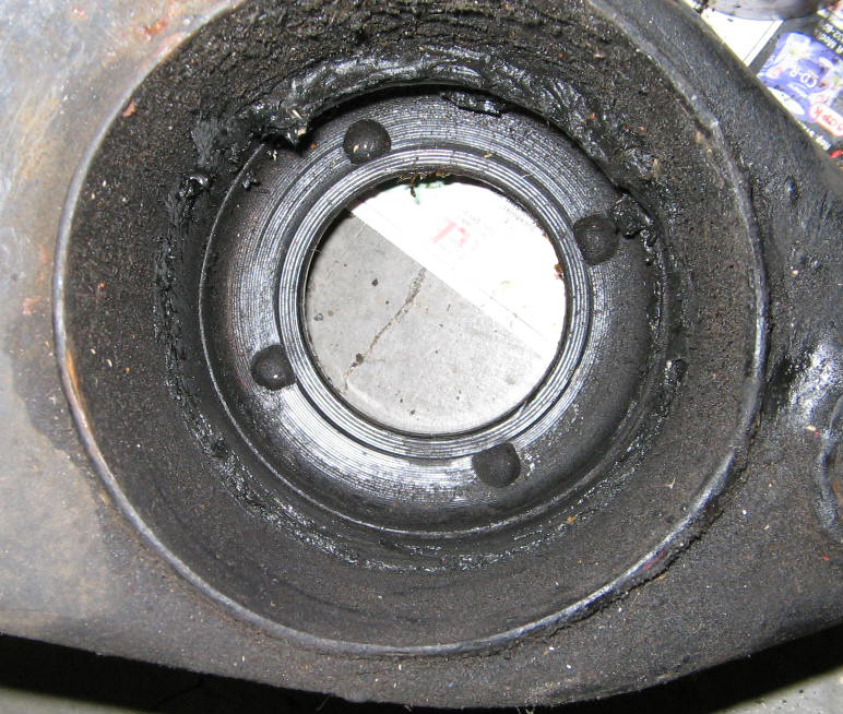
Posted by: Gint Feb 21 2009, 08:53 AM
Question... the inside of the trailing arm looks as though it has a plastic sleeve in there... am I seeing this correctly? The reason I ask is that I was planning on bringing both trailing arms to the local metal cleaner and have the grease and grime taken care of before I have them powdercoated. However, if these are dipped, the plastic will melt. Anyone know for sure? There's just too much grease in there still for me to get a good look.
I also need to call my local powdercoater and ask him how dirty a piece he'll accept. I know media blasting can clean parts up, but these are really dirty...
There is no plastic in there. Just grease... and dirt.
Posted by: kconway Feb 21 2009, 09:07 AM
Did all of the bearing come out? Isn't there suppose to be a cover over the balls?
Posted by: Eric_Shea Feb 21 2009, 11:04 AM

Posted by: Jeff Bowlsby Feb 21 2009, 11:30 AM
Please post the specs of the items needed to fab this bearing puller?
Gud yob mon...
And the result! Held the big bolt with a Vice Grip, turned the nut, and the bearing came out like buttah!
Attached image(s)

Posted by: MrKona Feb 21 2009, 12:29 PM
Yup, thanks guys. This morning I stuck a magnet onto it, you are right, it's all metal. Off to the metal cleaner these go for a bath.
Posted by: MrKona Feb 21 2009, 12:36 PM
Please post the specs of the items needed to fab this bearing puller?
Gud yob mon...
And the result! Held the big bolt with a Vice Grip, turned the nut, and the bearing came out like buttah!
Thanks Jeff. I used an 8" x 3/4 " bolt and appropriate nut. Of course, different threaded pieces could work. The important parts are: 1) Black piece, which is a "3" fitting cleanout adapter" from the plumbing section of the hardware store. The small end has a 3" ID and just shy of 3.5" OD. The large end (which rest on the trailing arm) has an ID of 3.5" and an OD of 4". 2) 2" diameter washer which mates with the bearing. 3) 3.5" large washer which rests on top of the black plumbing piece.
I added a couple extra washers on top of the large washer as you can see from the pics. This really wasn't necessary. Only needed if the nut is too small for the hole in the large washer.
Also, If I really wanted to get fancy and avoid holding the threads with a Vice grip, I could have added two additional nuts and cinched them tight to one another, then held one with a wrench to avoid gnarling up the threads.
Posted by: MrKona Feb 21 2009, 12:39 PM
Did all of the bearing come out? Isn't there suppose to be a cover over the balls?
Yup, it's there, it all came out. Hard to see with all the dirt and grease...
Posted by: Jeff Bowlsby Feb 21 2009, 10:21 PM
Thanks Bryan! That saves me some time...
Please post the specs of the items needed to fab this bearing puller?
Gud yob mon...
And the result! Held the big bolt with a Vice Grip, turned the nut, and the bearing came out like buttah!
Thanks Jeff. I used an 8" x 3/4 " bolt and appropriate nut. Of course, different threaded pieces could work. The important parts are: 1) Black piece, which is a "3" fitting cleanout adapter" from the plumbing section of the hardware store. The small end has a 3" ID and just shy of 3.5" OD. The large end (which rest on the trailing arm) has an ID of 3.5" and an OD of 4". 2) 2" diameter washer which mates with the bearing. 3) 3.5" large washer which rests on top of the black plumbing piece.
I added a couple extra washers on top of the large washer as you can see from the pics. This really wasn't necessary. Only needed if the nut is too small for the hole in the large washer.
Also, If I really wanted to get fancy and avoid holding the threads with a Vice grip, I could have added two additional nuts and cinched them tight to one another, then held one with a wrench to avoid gnarling up the threads.
Posted by: kwales Feb 22 2009, 10:04 AM
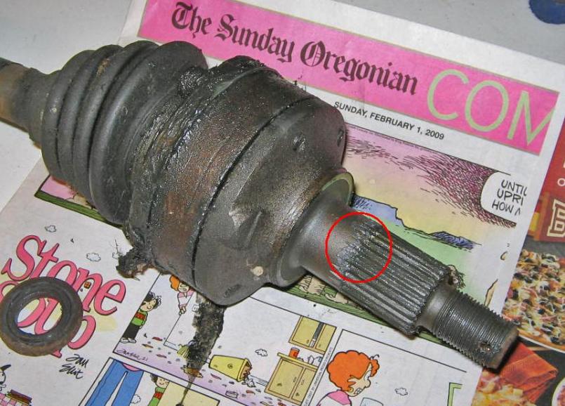
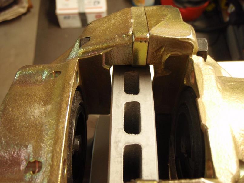
Looking at the splines, there are two different approaches used to make them.
The ones in your find are machined using a circular cutter that travels longitudinally along the lenght of the spline area. That type of machining would produce the characteristic "V" at the end of the groove (see red arrow).
How would you do it in 1970's? Hans in the machine shop would attach to a mill and enables him to rotate the axle stub around the shaft axis in an increment of 360 degrees divided by the number of splines. Once the axle is held at the first groove positon positioned, Hans moves the bed into the axle to create a circular slot like a keyway, then Hans makes the bed travel longitudinally to cut the slot.
Then Hans cranks the axle stub away from the cutter, and moves the bed back to the start position. He then rotates the axle by one spline amount and resarts the process. Remember, the whole time he is cranking this thing back and forth by hand to make the splines..... Or, maybe a rotary indexing tooling.
For the production splines, you produce the square end in the groove (see blue arrows). To do this, you might use a rotary approach where a really hard spline tool is made that resembles a gear is both pressed into the axle (unhardened state) and and rotated around the axle shaft to produce the splines. Or, a linear broach could also make the square ends to the grooves.
Prolly a few more processes but the point is, they may be a handmade very low volume part.
Ken
Attached image(s)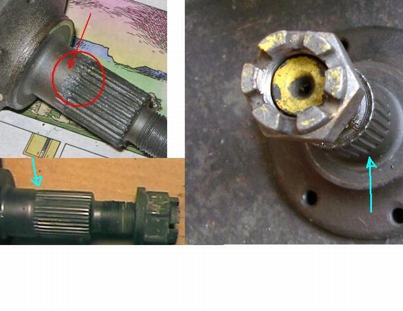
Posted by: MrKona Feb 22 2009, 12:23 PM
Looking at the splines, there are two different approaches used to make them.
The ones in your find are machined using a circular cutter that travels longitudinally along the lenght of the spline area. That type of machining would produce the characteristic "V" at the end of the groove (see red arrow).
How would you do it in 1970's? Hans in the machine shop would attach to a mill and enables him to rotate the axle stub around the shaft axis in an increment of 360 degrees divided by the number of splines. Once the axle is held at the first groove positon positioned, Hans moves the bed into the axle to create a circular slot like a keyway, then Hans makes the bed travel longitudinally to cut the slot.
Then Hans cranks the axle stub away from the cutter, and moves the bed back to the start position. He then rotates the axle by one spline amount and resarts the process. Remember, the whole time he is cranking this thing back and forth by hand to make the splines..... Or, maybe a rotary indexing tooling.
For the production splines, you produce the square end in the groove (see blue arrows). To do this, you might use a rotary approach where a really hard spline tool is made that resembles a gear is both pressed into the axle (unhardened state) and and rotated around the axle shaft to produce the splines. Or, a linear broach could also make the square ends to the grooves.
Prolly a few more processes but the point is, they may be a handmade very low volume part.
Ken
Ken, Thanks - Very interesting information...
- Bryan
Posted by: MrKona Feb 22 2009, 09:25 PM
So what's the secret to removing the rubber bushings from the trailing arms? I heated up the metal around the bushing today, hoping to be able to pull it out in one piece. Yeah, right... Instead, it was bit, bit, by tiny bit of rubber. Is there a trick to it?
Posted by: Eric_Shea Feb 22 2009, 10:53 PM
I use a simple press. It would probably pay for itself with this job. It's one of those things you can't go wrong with at HF for $99 bucks.
Step 1: Set the shelf to the proper height. Heat the shaft and press it through the fist bushing. You can see the bushing melt like butter as the hot shaft goes through it (settle down Slits).
Step 2: Take a large screwdriver to the "inside" of the now exposed bushing and pry up. You should have to do this 3x before the bushing pops out.
Step 3: Lower the shelf one notch, heat the shaft again and press it back through to it's original position.
Step 4: Raise the shelf one notch, heat the shaft and press it the remaining way through until it pops out.
Step 5: Repeat step 2.
Hope that helps but... if you don't have a press or don't intend on getting one, maybe take these notes to a friend or shop that has one.
Others will weigh in and tell you to burn them out and stink up your garage.
Posted by: MrKona Feb 22 2009, 11:00 PM
I use a simple press. It would probably pay for itself with this job. It's one of those things you can't go wrong with at HF for $99 bucks.
Step 1: Set the shelf to the proper height. Heat the shaft and press it through the fist bushing. You can see the bushing melt like butter as the hot shaft goes through it (settle down Slits).
Step 2: Take a large screwdriver to the "inside" of the now exposed bushing and pry up. You should have to do this 3x before the bushing pops out.
Step 3: Lower the shelf one notch, heat the shaft again and press it back through to it's original position.
Step 4: Raise the shelf one notch, heat the shaft and press it the remaining way through until it pops out.
Step 5: Repeat step 2.
Hope that helps but... if you don't have a press or don't intend on getting one, maybe take these notes to a friend or shop that has one.
Others will weigh in and tell you to burn them out and stink up your garage.
Eric, thanks as always for your advice... This is not something I would have figured out on my own...
Posted by: MrKona Mar 20 2009, 03:32 PM
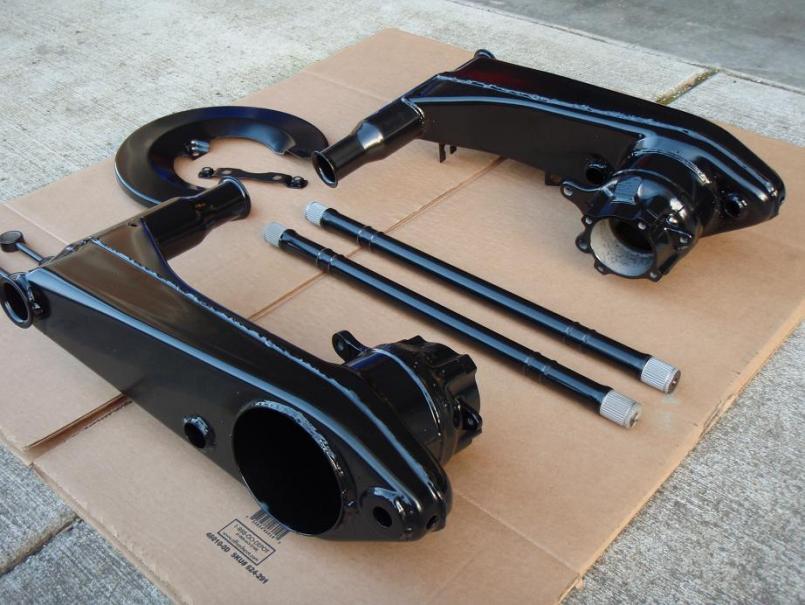
Just got a pile of parts back from the metal cleaner today. I'll deliver these to the powder coater next week. The trailing arms in particular were covered with CV grease and caked dirt. All gone now.
I also had a rusty front cross bar and A-arms for the front done, as you can see. I'm pretty happy with how nicely they cleaned up.
Attached thumbnail(s)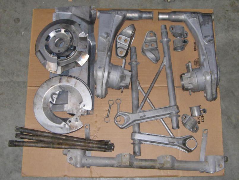
Posted by: MrKona Mar 20 2009, 03:33 PM
Another...
Attached thumbnail(s)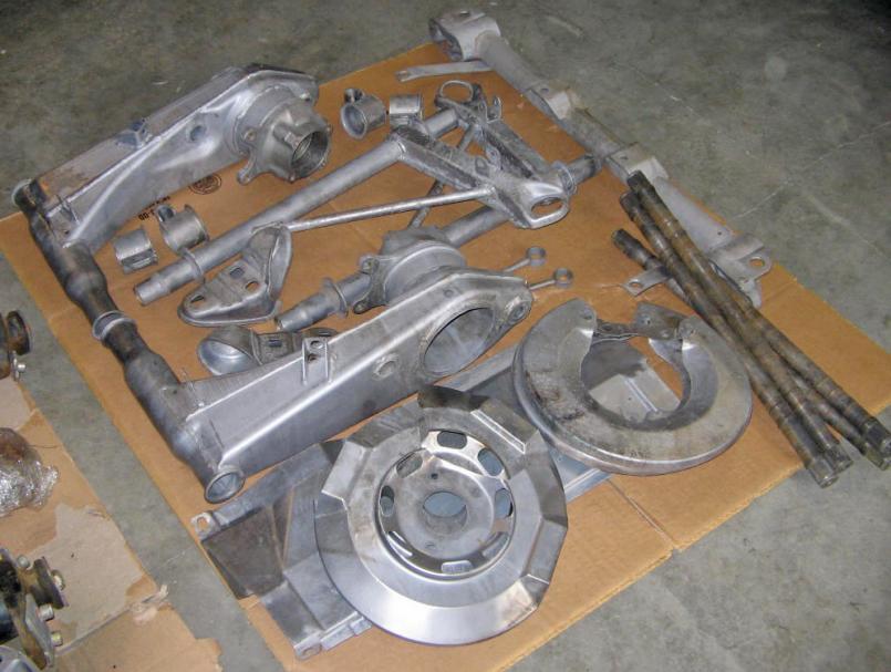
Posted by: MrKona Mar 20 2009, 03:34 PM
Eric - I'm going to send the clean stub axles and a couple other small pieces to you for zinc plating.
Attached image(s)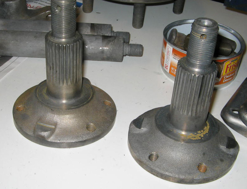
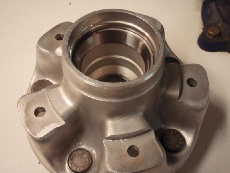
Posted by: MrKona Mar 20 2009, 03:39 PM
Also had the hubs cleaned. I'm going to blast off some surface rust that's beginning to form and paint the back side.
Attached thumbnail(s)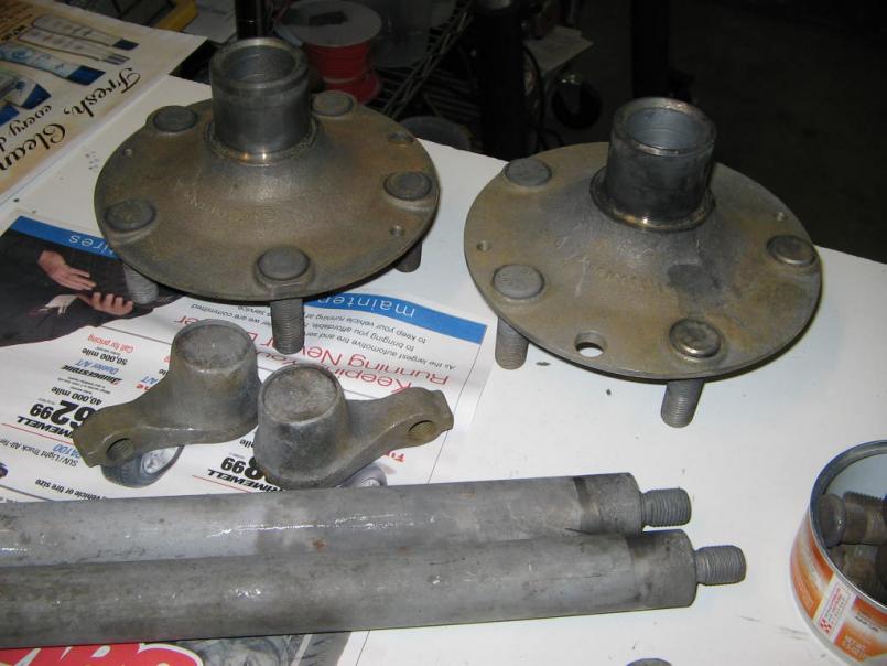
Posted by: MrKona Apr 3 2009, 08:16 PM
I have front and rear suspension projects going, so I'm going to merge them into this thread. The front suspension project is http://www.914world.com/bbs2/index.php?showtopic=92383&hl=MrKona
I picked up powder coated parts today. As funds free up, I'll install new bearings, bushings, and hardware. My goal is to have my car back on the road this summer. It's been way too long since I've had this thing on the road.
Unfortunately, as I readying parts for the powder coater, I discovered that one of the rear brake dust plates was cracked at the middle bolt hole. I then took both plates of my car - and both of them were cracked too! I'm going to hold off on coating until I can find one that is not cracked.
Attached thumbnail(s)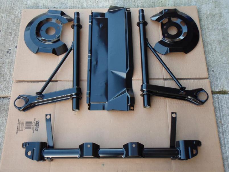
Posted by: charliew Apr 4 2009, 12:49 PM
I guess this means you will use the solid rear rotors and their matching size calipers? How much did they charge to clean the parts? The only people I know that do that are motor shops and they won't do it unless you use them to build the motor.
Posted by: MrKona Apr 4 2009, 02:04 PM
I guess this means you will use the solid rear rotors and their matching size calipers? How much did they charge to clean the parts? The only people I know that do that are motor shops and they won't do it unless you use them to build the motor.
Yep, I'll use 914-4 rear calipers and solid rotors. I already have a rebuilt pair. There is a place in Portland that does nothing but metal cleaning... from small parts to entire car bodies. http://www.americanmetalcleaning.com/. All the stripped parts in the picture, plus four CV joints, hubs, stub axles, and strut caps was around $250. I have another box of rusty, grimy exhaust pipes, intake tubes, and plenum in a box to drop off on Monday. I'm going to try home painting the exhaust pipes with VHT paint to save $$$.
The Powder coating was more expensive... to the point that I was up this morning thinking about it...

Posted by: MrKona Apr 16 2009, 10:21 PM
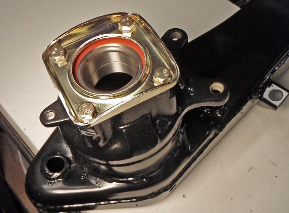
I'm installing the rear bearings tonight. I started the bearing by tapping it in as straight as possible with a rubber mallet and then finished it with a press. On good advice from an expert here on the board, I pressed the arm down onto the bearing rather than pressing the bearing into the arm.
It was a little tricky keeping the bearing straight while in the press. I rested the arm and bearing on a press plate. Then I laid a 1/4" steel plate on the back side of the arm, across the larger opening, with a newspaper between the plate and arm so as not to scratch the powder coat. I then pressed a little, repositioned the arm slightly, pressed again, and so on until the bearing was almost all the way in, then I applied more pressure and the bearing seated nicely. Sorry no pictures, I was using both hands holding the arm in the press and I didn't want my wife to take pictures in case I really screwed something up.
I had the bearing caps cleaned and zinc plated and I'm really happy with the results. Finished it off with new zinc plated bolts and wave washers, torqued to 18 ft/lbs.
Attached thumbnail(s)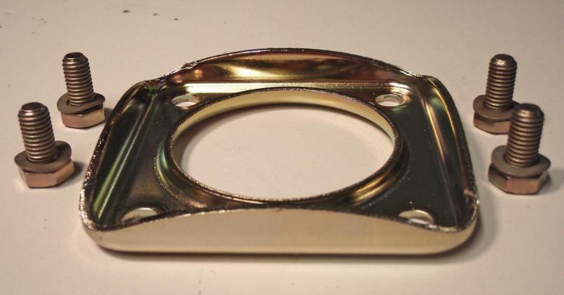
Attached image(s)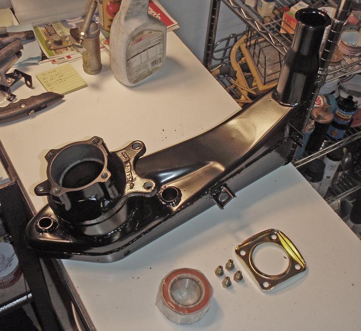
Posted by: charliew Apr 18 2009, 09:47 AM
If it's not too late. I have had real good luck with Eastwoods Stainless Steel paint for exhaust. I have used it on blasted bug headers and a k5 blazer exhaust and a case tractor exhaust and it has been on the k5 and case for several years and except for the bolts on the clamps it looks great. It's supposed to be cured at 400 but I used a torch and was careful not to burn it while I used a lazer temp gun to monitor the temps to cure it. The last time I just let the bug exhaust do the cooking. I always let the paint cure though before heating it up.
The only thing was the ss paint was really hard to clean out of the touchup gun and I ended up with some flake in a clear coat on a honda tank later on.
I got it in a red pint can. I'm pretty sure it was from Eastwood but it might have been Restomotive or por 15 as most people say.
Posted by: MrKona Apr 18 2009, 01:25 PM
If it's not too late. I have had real good luck with Eastwoods Stainless Steel paint for exhaust. I have used it on blasted bug headers and a k5 blazer exhaust and a case tractor exhaust and it has been on the k5 and case for several years and except for the bolts on the clamps it looks great. It's supposed to be cured at 400 but I used a torch and was careful not to burn it while I used a lazer temp gun to monitor the temps to cure it. The last time I just let the bug exhaust do the cooking. I always let the paint cure though before heating it up.
The only thing was the ss paint was really hard to clean out of the touchup gun and I ended up with some flake in a clear coat on a honda tank later on.
I got it in a red pint can. I'm pretty sure it was from Eastwood but it might have been Restomotive or por 15 as most people say.
Thanks Charlie. It's not too late. The steel exhaust pieces are at the metal cleaner now being cleaned. I'll do a search on the paint you're talking about.
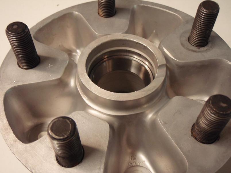
Posted by: MrKona Apr 18 2009, 01:29 PM
I installed the hubs today using the same screw mechanism I used to pull the original bearings. Worked great.
Started out with nice clean hubs..
Taped up the powder coated surface to avoid scratches.
Attached thumbnail(s)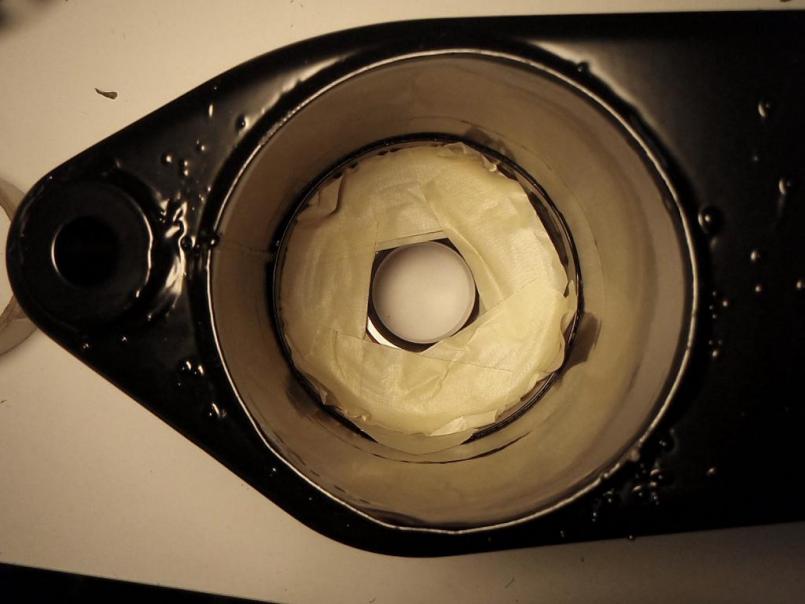
Attached image(s)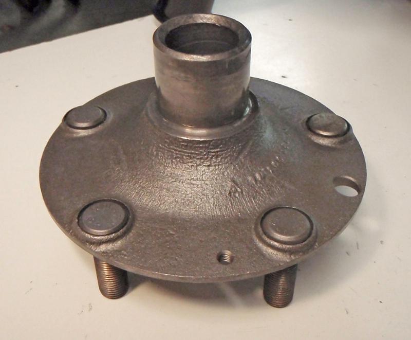
Posted by: MrKona Apr 18 2009, 01:30 PM
Laid a couple washers on the tape. The washer was large enough that it contacted the control arm surface and not the bearing.
Attached thumbnail(s)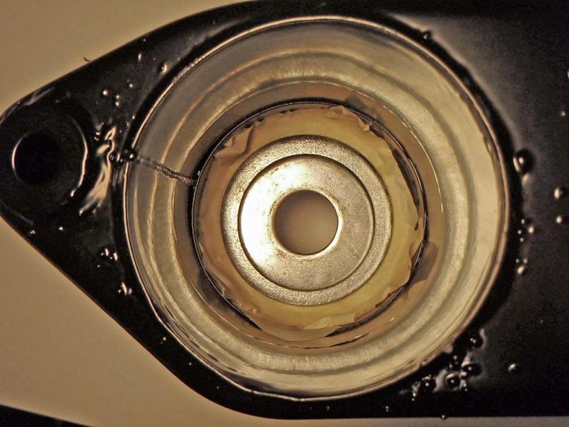
Posted by: MrKona Apr 18 2009, 01:31 PM
The "screw mechanism." Put a light coat of grease on the hub surface.
Attached thumbnail(s)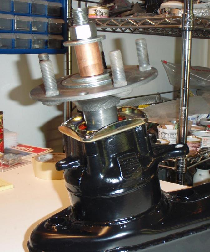
Posted by: MrKona Apr 18 2009, 01:33 PM
And the final result!
Attached thumbnail(s)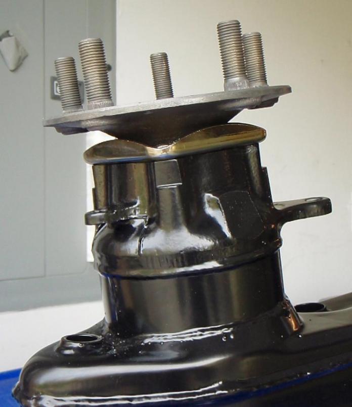
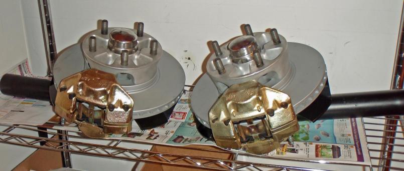
Posted by: MrKona Apr 30 2009, 10:35 PM
I pressed in the races from new bearings and adjusted the adjusting clamping nut on the strut housing spindle so that the washer just moves, as shown in the 911 Haynes manual. Can someone please confirm if the picture looks correct? It's the distance of the hub body and the distance ring. Is this correct? The reason I ask is that the caliper body does not appear 'perfectly' centered over the disk.
I installed the pads and they both clear the disk just fine...
Although I believe that I pressed the inner race all the way into the hub, I'd like some more sets of eyes to look at this before I tap the dust cap on all the way. Thanks.
Attached thumbnail(s)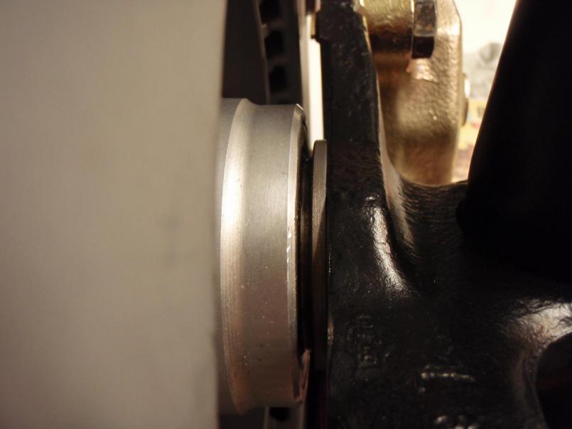
Posted by: MrKona Apr 30 2009, 10:36 PM
One more showing the assembly coming together.
Attached thumbnail(s)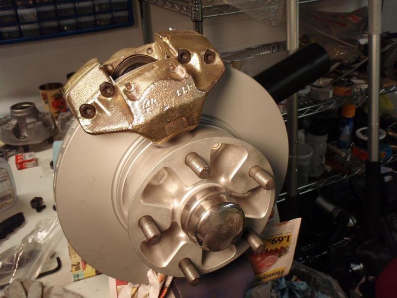
Posted by: jaxdream May 1 2009, 07:30 AM
And the final result!
They look great , what are you going to use for a park / emergency brake ??
Jaxdream
Never mind , read the earlier post.
Still all looks very good.

Posted by: Jeffs9146 May 1 2009, 08:25 AM
If it is not in all of the way the brakes would not line up! I think you are ok
Posted by: MrKona May 1 2009, 09:49 AM
If it is not in all of the way the brakes would not line up! I think you are ok
Thanks... would look even better had a remembered to install the dust plate first! Du-oh!
Posted by: nocones May 1 2009, 12:56 PM
Great work, and really helpful thread!
I'm just about done putting my car back together, but for me it all went back together dirty. After a suitable shake-down I hope to take it apart again this winter and, like you, replace all bearings/bushings and totally clean/powdercoat the suspension parts.
Posted by: MrKona May 1 2009, 11:23 PM
Assembly, part II tonight. Had to remove the hub and reinstall after attaching the brake dust shield. Once I put the dust shield on, I didn't have that strange space between the distance ring and hub like I did last night. Imagine that...
Per Haynes, torqued dust shield bolts to 18 ft/lbs. I used SS bolts and new wavy washers.
Also did a final visual check to make sure the new races were pressed in all the way. They were... Prior to pressing in the races, I heated the hubs in a 275 degree oven. I used a hydraulic press to install them, along with a correct size socket and large washers to rig up a way to press them in.
Attached thumbnail(s)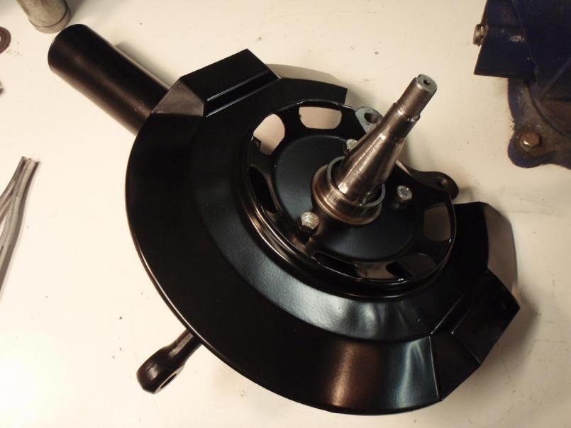
Posted by: MrKona May 1 2009, 11:29 PM
Inner bearing in, and dust shield on, tapped in with a rubber mallet.
Attached thumbnail(s)
Posted by: MrKona May 1 2009, 11:32 PM
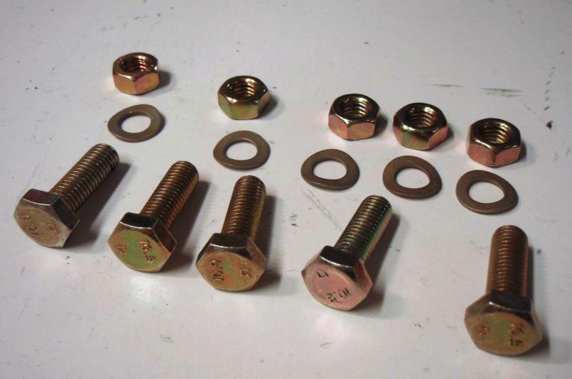
Disk ready for install of hub.
New yellow zinc plated hardware.
Attached thumbnail(s)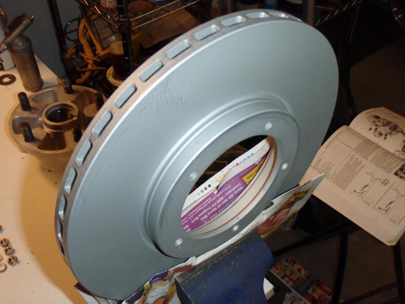
Posted by: MrKona May 1 2009, 11:34 PM
"Silver and Gold" 
Hub to disk nuts torqued to 17 ft/lbs.
Attached thumbnail(s)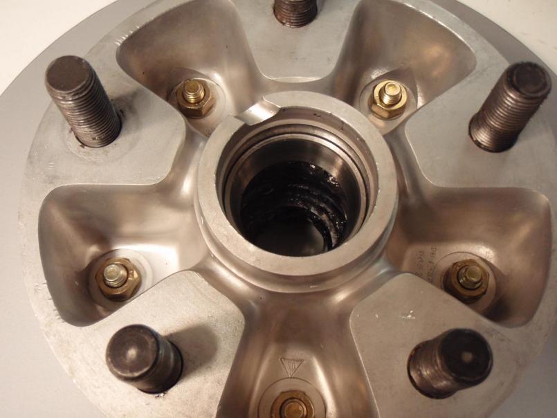
Posted by: MrKona May 1 2009, 11:38 PM
Ready for the dust cap. Per haynes, after installing the outer bearing, tighten the clamping nut to approximately 10 ft/lbs to seat the bearings. Than loosen it until the thrust washer can just be moved, tighten clamping nut screw.
Done, sitting on the shelf for eventual installation.
Attached thumbnail(s)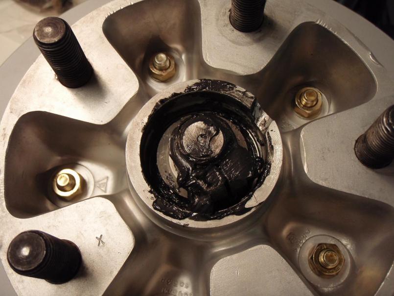
Posted by: MrKona Nov 22 2009, 01:39 PM
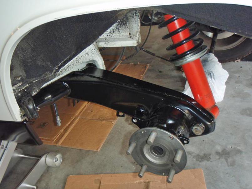
I'm half way there with the five lug installation. Yesterday, I installed the rear trailing arms. As you can see from the pictures, I installed the rear trailing arms bushings from PMB, and added zerks.
Also took the time to replace the SS braided brake lines the previous owner had installed with rubber lines.
Attached thumbnail(s)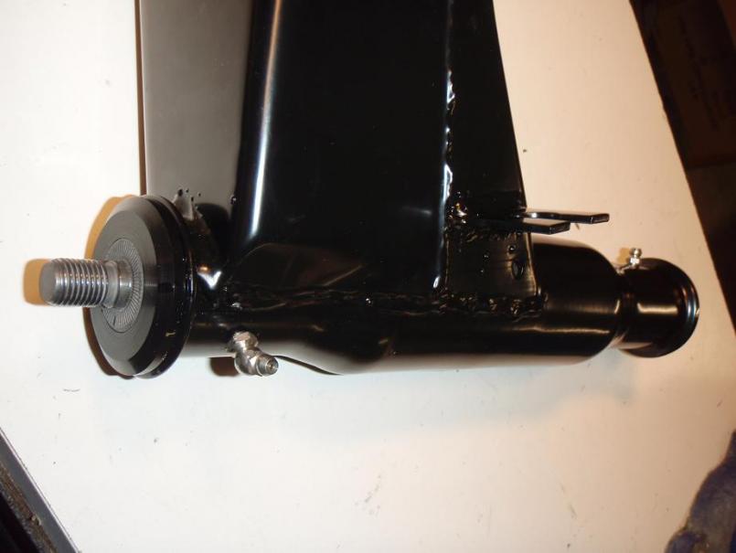
Posted by: MrKona Nov 22 2009, 01:42 PM
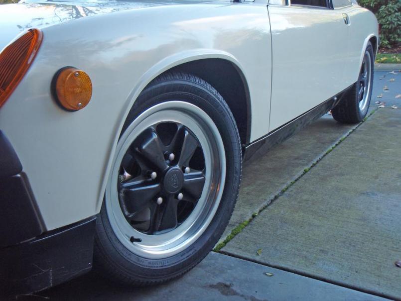
16x6 Fuchs. Two down, two to go.
Attached thumbnail(s)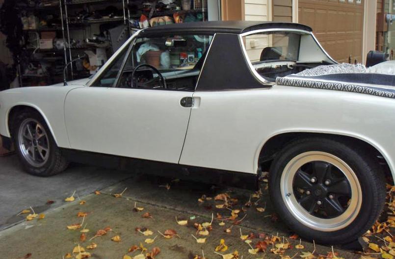
Attached image(s)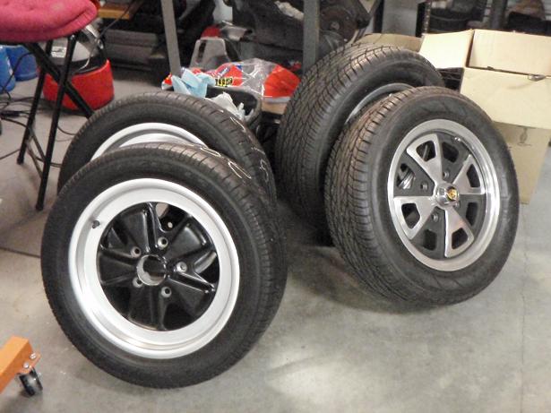
Posted by: Eric_Shea Nov 22 2009, 01:54 PM
Nice work Bryan. 
Posted by: MrKona Nov 27 2009, 06:42 PM
Installed the fronts. Also installed new ball-joints and tie rod ends as well. The old tie rod boots were ripped and who-knows-how-old. Steel braided lines were replaced with new rubber lines.
It worked out well that the new suspension was the later 911 strut that uses the wedge pin like the 914. I was able to simply transfer the Bilstein inserts.
The problem with putting new stuff on the car is that it makes the surrounding areas look that much dirtier. I have to scrub the inner wheel well this weekend. I previously had a cross member and A-arms powder coated, but opted to leave the existing pieces on the car and just replaced the struts. The power coated pieces will wait until I do a more extensive restoration on this car one day.
Time to change my avatar!
Attached thumbnail(s)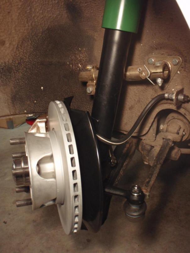
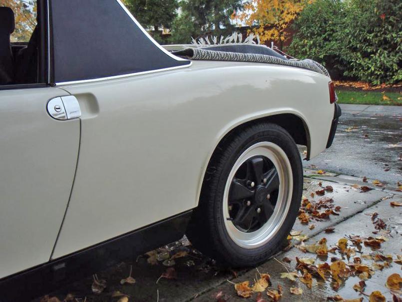
Posted by: SirAndy Nov 27 2009, 06:53 PM
Time to change my avatar!
Check your rear alignment!
Looks like you're running positive camber ...
 Andy
Andy
Posted by: MrKona Nov 27 2009, 06:57 PM
Time to change my avatar!
Check your rear alignment!
Looks like you're running positive camber ...
AndyThanks Andy. Once I finally get this thing running again, my first stop will be at a good alignment shop.
Posted by: JRust Nov 27 2009, 10:14 PM
Bryan car is looking great! Nice work man. Can't wait to see you driving it 
Posted by: MrKona Dec 1 2009, 12:07 AM
Bryan car is looking great! Nice work man. Can't wait to see you driving it
Thanks Jamie. Likewise with the Creamsicle!

Posted by: MrKona Dec 1 2009, 12:18 AM
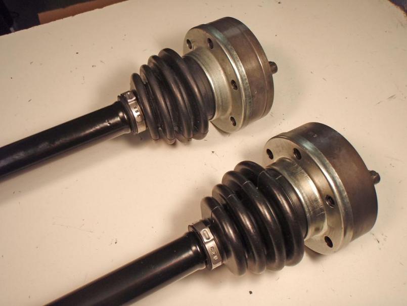
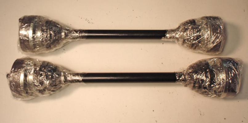
Finished up the axles tonight. Previously had a set of axles powdercoated. I disassembled, cleaned, and repacked the CVs and reinstalled with new boots and clamps.
Took some pictures and then wrapped up the CVs to avoid spreading any more CV grease - messy stuff to say the least; went through a lot of paper towels and disposable gloves.
Attached thumbnail(s)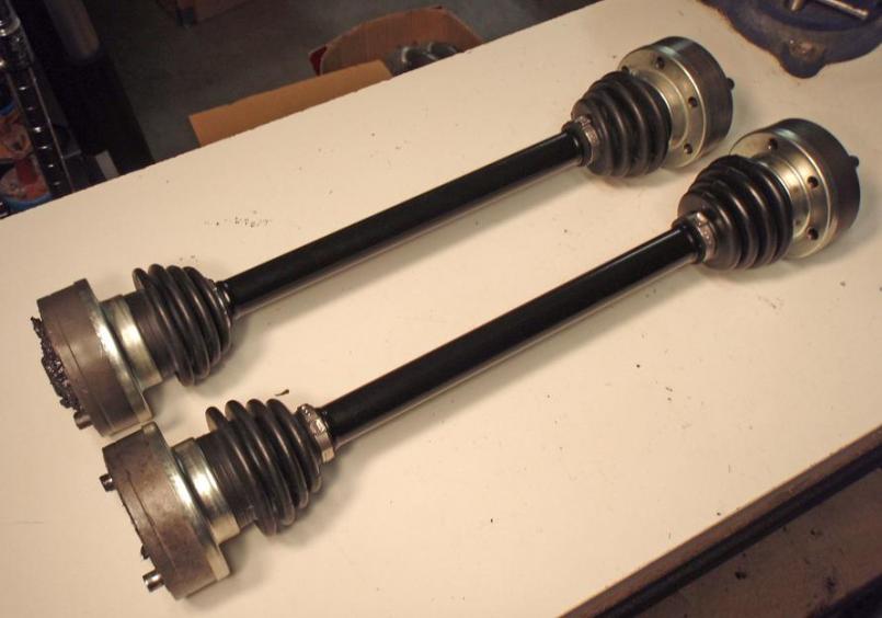
Posted by: davesprinkle Dec 1 2009, 08:06 AM
Time to change my avatar!
Check your rear alignment!
Looks like you're running positive camber ...
AndyThanks Andy. Once I finally get this thing running again, my first stop will be at a good alignment shop.
Andy,
I saw this car the other day. There's no engine or tranny, so the car is sitting quite high. This at least partially explains the positive camber.
Posted by: kconway Dec 1 2009, 08:51 AM
Finished up the axles tonight. Previously had a set of axles powdercoated. I disassembled, cleaned, and repacked the CVs and reinstalled with new boots and clamps.
Took some pictures and then wrapped up the CVs to avoid spreading any more CV grease - messy stuff to say the least; went through a lot of paper towels and disposable gloves.
Where do you get those clamps and do you need a "single purpose" tool to install them?
Kev
Posted by: MrKona Dec 1 2009, 10:55 AM
Finished up the axles tonight. Previously had a set of axles powdercoated. I disassembled, cleaned, and repacked the CVs and reinstalled with new boots and clamps.
Took some pictures and then wrapped up the CVs to avoid spreading any more CV grease - messy stuff to say the least; went through a lot of paper towels and disposable gloves.
Where do you get those clamps and do you need a "single purpose" tool to install them?
Kev
I got the clamps at McMaster Carr, here's the http://www.mcmaster.com/#ear-hose-clamps/=4qsj63, the clamps I got say "34.6" and they fit well, although I can't remember the part number that translates to McMaster Carr (I got the "gap free pinch with tongue and groove"). You'd have to measure to be sure. Or you can just PM me your address and I'll send some. I've got leftovers and I hope not to do this job again soon.
There is a special tool. Google "CV joint pliers" and you'll see it. However, I just used a Channel Lock cutting plier and it worked fine. It looks just like the tool that McMaster Carr advertises for installing these.
- Bryan
Powered by Invision Power Board (http://www.invisionboard.com)
© Invision Power Services (http://www.invisionpower.com)