Printable Version of Topic
Click here to view this topic in its original format
914World.com _ The Paddock _ Anyone got rid of the relay board?
Posted by: moggy Aug 13 2013, 12:43 PM
Need to install the custom oil tank for the dry sump system in the space to the left of the engine i.e. where the relay board is. I was thinking of simply moving the relay board but on further investigation I realised the only active part on there is the regulator for the alternator. The rest of the board just seems to be a pass through to the wiring at the back (mostly lights). Has anyone simply done away with this board for the sake of simplicity? any tips, pictures or wiring sketches to give me a head start?
Cheers
Moggy
Posted by: bulitt Aug 14 2013, 06:43 AM
I'm going there. Apparently been done many times before (several threads).
You need a male connector to connect to the female wiring harness. Patrick motorsports sells them, they also sell plug and play harnesses. You will need to add a light or 70ohm resistor to excite the alternator. An ammeter may work for this? Not sure. Here is some reading.
http://www.914world.com/bbs2/index.php?showtopic=211461&hl=relay++board
http://www.914world.com/bbs2/index.php?showtopic=162350&hl=relay++board
http://www.914world.com/bbs2/index.php?showtopic=142289&hl=relay++board
http://www.914world.com/bbs2/index.php?showtopic=127639&hl=relay++board
http://www.914world.com/bbs2/index.php?showtopic=97852&hl=
http://www.patrickmotorsports.com/part/ele-911-612-113-05/
Posted by: moggy Aug 14 2013, 10:29 AM

I'm going there. Apparently been done many times before (several threads).
You need a male connector to connect to the female wiring harness. Patrick motorsports sells them, they also sell plug and play harnesses. You will need to add a light or 70ohm resistor to excite the alternator. An ammeter may work for this? Not sure. Here is some reading.
http://www.914world.com/bbs2/index.php?showtopic=211461&hl=relay++board
http://www.914world.com/bbs2/index.php?showtopic=162350&hl=relay++board
http://www.914world.com/bbs2/index.php?showtopic=142289&hl=relay++board
http://www.914world.com/bbs2/index.php?showtopic=127639&hl=relay++board
http://www.914world.com/bbs2/index.php?showtopic=97852&hl=
http://www.patrickmotorsports.com/part/ele-911-612-113-05/
Awsome, thanks Bob. I did a search but couldn't find anything relevant - you're obviously better at it than me

Some bed time reading for me tonight

Posted by: stugray Aug 14 2013, 10:22 PM
I removed mine entirely.
I replaced the alt idiot light with a FLAPS LED indicator and a 70 Ohm resistor in parallel.
The resistor provides enough current to energize the field winding.
The LED does not by itself.
It seems to be working, but I havent had my car running long enough to know how well I am charging. I started out with a weak alternator to boot.
http://www.914world.com/bbs2/index.php?showtopic=211461&hl=relay
Stu
Posted by: bulitt Aug 15 2013, 08:15 AM
Heres the best pic of the relay board I can find. With a zoom feature and clear.
You can see the wires that basically run right through the board and the remaining
wires/relays you may have to deal with. The top numbers 3&4 should read "back up lights" not brake lights
http://www.914world.com/bbs2/index.php?act=Attach&type=post&id=229959
Posted by: stugray Aug 28 2013, 08:28 AM
That "Plug for Alternator" will unplug from the relay board and plug directly in to the voltage regulator.
If you splice the Blue wire from above (2-From Alternator Light to D+ on Alt harness) into the D+ (red wire in Alt harness) it will work.
Stu
Posted by: moggy Sep 6 2013, 07:50 AM
To to get closure on this, cos' there's nothing worse than doing a search on something finding the ideal thread then finding out the guy who started it never concluded what happened
This was a real easy task!
After taking out the relay board and cutting out all the mounts for it (I needed the area for a dry sump oil tank), I then took apart the plugs on the ends of the 2 main cables that come into the relay board. Using the various circuit diagrams helpfully provided above, I stripped out and binned a load of the wires that weren't actually needed (which from memory was about half). Then the ones that are left (apart from one for the alternator charging light) are simply spliced individually together i.e. they are only pass through wires on the relay board anyway. Use the relay board circuit diagram and the colour coding to figure out which ones these are.
Then lastly I mounted the regulator on the tinware, plugged the alternator cable directly into it, using the standard plug, and simply spliced in the dashboard signal wire.
Simples!!! Took me about an hour.
Now I've got a whole load of space for the tank, simpler wiring, a little less weight, and less concern about water ingress through the engine grill onto that redundant relay board.
Now to take some pictures of the new shiny oil tank 
Posted by: Jeff Bowlsby Sep 9 2013, 08:47 PM
How is it redundant...you should replace the removed relays and fuses that were on it with something performing similar functions and assuming you dont need the fuel injection connection:
Main power relay
Rear window relay and fuse-optional
Heater fan relay
Fuel pump relay
Main power fuse
And, everything is hardwired together making the ignition and alternator harnesses harder to replace.
Posted by: r_towle Sep 10 2013, 08:23 PM
How is it redundant...you should replace the removed relays and fuses that were on it with something performing similar functions and assuming you dont need the fuel injection connection:
Main power relay
Rear window relay and fuse-optional
Heater fan relay
Fuel pump relay
Main power fuse
And, everything is hardwired together making the ignition and alternator harnesses harder to replace.
Rally car.
No rear window relay needed
No heter fan needed
No fuel pump relay needed, he wired it up front
What main power relay are you talking about? Main power for the fuel injection, but not for the main power to the cabin fuse panel.
Posted by: Jeff Bowlsby Sep 10 2013, 11:28 PM
Relay 74 and the 25A main fuse, primary protection for the car.
Attached image(s)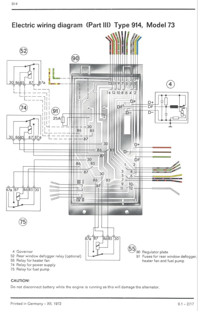
Posted by: moggy Sep 12 2013, 04:14 AM
Relay 74 and the 25A main fuse, primary protection for the car.
Not sure what that relay 74 and fuse are for but they were never on my relay board since I've owned the car. Also, come to think of it I can't remember seeing it on a lot of 914's I've seen. Maybe it's something to do with FI (mine is carbs).
Posted by: Jeff Bowlsby Sep 12 2013, 09:16 AM
Check out a wiring diagram to see what those were for. Without that fuse, the stock fuel pump relay would not have worked. Without the main power relay other circuits would not have had power... there must have been some wiring mods at some point to get it to all work.
Powered by Invision Power Board (http://www.invisionboard.com)
© Invision Power Services (http://www.invisionpower.com)