Printable Version of Topic
Click here to view this topic in its original format
914World.com _ The Paddock _ Strain gage for
Posted by: Randal Apr 27 2009, 02:23 PM
Anyone know of a strain gage that measures in lbs or kg's that I can use to measure the downforce of my new rear spoiler. I plan on mounting it underneath the truck lid between the lid and the fiberglass frame. Like where the arrows are pointing: 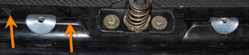
I figure if I can find something that reads the downward force I can just set it up with a video camera pointing at the gage, drive down the freeway. with the car on the trailer and get some readings.
Posted by: underthetire Apr 27 2009, 02:32 PM
http://www.omega.com/pressure/psc.html
Posted by: 6freak Apr 27 2009, 03:01 PM
seems to me if it was on the trailer it would not give you the correct reading ...should be in socalled clean air ..JMO
Posted by: Randal Apr 27 2009, 03:22 PM

seems to me if it was on the trailer it would not give you the correct reading ...should be in socalled clean air ..JMO
Right, the cab on the truck would definitely disrupt the air, but I've got a full cover on the pickup bed and there's nothing between that and the rear spoiler - as I've already removed the windshield and rear glass on my car.
Posted by: Randal Apr 27 2009, 04:57 PM
http://www.omega.com/pressure/psc.html
Very very nice stuff. I think the load cells would be perfect, but super expensive.
Although I might not be looking at the right product....

Posted by: underthetire Apr 27 2009, 05:06 PM
http://www.omega.com/pressure/psc.html
Very very nice stuff. I think the load cells would be perfect, but super expensive.
Although I might not be looking at the right product....
295 each. Yep. not super cheap. You could have a permanent set up inside your car though.
Could you hook up a fish scale some how?
Posted by: J P Stein Apr 27 2009, 05:46 PM
A load cell wold be what you need....2 actually ...unless you can figure a way to concentrate the force on one spot. Fish scales require travel....which you don't have.
Posted by: type11969 Apr 27 2009, 09:06 PM
I would think that in order to get decent readings, you would have to put the load cells in series with the uprights . . . in other words the uprights would have to be cut. Otherwise the only load you would read in the load cell was if the spoiler was deflecting locally in the region of the load cell . . . and that would still be a bunk reading because the load would be shared with the uprights. Now you could potentially epoxy some strain gauges on the uprights and come up with a load based off of the output, the cross sectional area of the upright, and the geometry of the spoiler/uprights, but because the loading probably isn't purely compressive on the uprights, you are not going to get a true reading unless you go to some effort. Like multiple strain gauges around the periphery of both uprights to resolve the force and a datalogger. I guess it all depends on how accurate you want the result to be.
Posted by: Randal Apr 27 2009, 10:14 PM
I would think that in order to get decent readings, you would have to put the load cells in series with the uprights . . . in other words the uprights would have to be cut. Otherwise the only load you would read in the load cell was if the spoiler was deflecting locally in the region of the load cell . . . and that would still be a bunk reading because the load would be shared with the uprights. Now you could potentially epoxy some strain gauges on the uprights and come up with a load based off of the output, the cross sectional area of the upright, and the geometry of the spoiler/uprights, but because the loading probably isn't purely compressive on the uprights, you are not going to get a true reading unless you go to some effort. Like multiple strain gauges around the periphery of both uprights to resolve the force and a datalogger. I guess it all depends on how accurate you want the result to be.
I'd be happy with+/- 5lbs. To be honest, I don't have a clue whether the old ducktail or the ducktail with my new extension works at all.
But if at 45mph it works and I start seeing more understeer then I know I need to make some adjustments.
Posted by: J P Stein Apr 28 2009, 07:42 AM
But if at 45mph it works and I start seeing more understeer then I know I need to make some adjustments.
When setting up my car I did it so it would rotate around tight corners....30mph or so...with a slight tendency to oversteer. It even works most of the time.

Pushing at slow speed is a time killer...not to mention buggering up your planned line......to be avoided at all costs, I figure.
The end result is a strong tendency to oversteer every where else. That is why:
1) I've never bothered with a front splitter. There's no aero help at 30 mph, IMO
2) I went with the tallest spoiler I could from the gitgo.....trying to keep the back end nailed down on the higher speed stuff.....50mph & up. It still oversteers, just not as badly.
My set up is a compromise and it's been known to get caught out at either end of the spectrum.

Posted by: 6freak Apr 28 2009, 08:09 AM
I agree with the 30mph statement ...and its probable true at even higher speeds! say around 60+ mph. Ground effects just are not what people think they are or do .you need a pretty good amount of speed to over come the amount of drag they actualy create...to go from drag and slowing the car, to down force helping the car hold the road ...maybe that university professor will chim in again with he`s fancey charts? he showed it once before and i cant find it ..This is all just my opinion ,kinda like thinking out loud ...good luck with everything i really do hope it works for you
Mike
Posted by: J P Stein Apr 28 2009, 05:04 PM
I agree with the 30mph statement ...and its probable true at even higher speeds! say around 60+ mph. Ground effects just are not what people think they are or do .
Mike
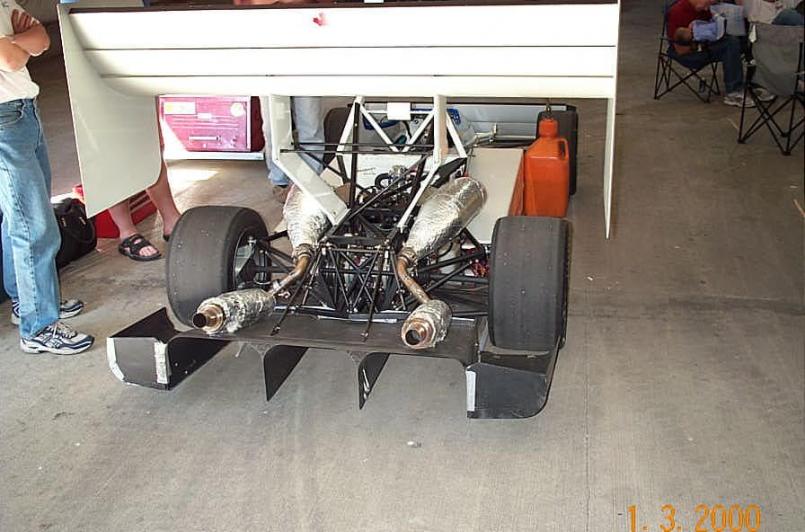
You've never seen Joe Chen's A Mod car run, eh? On a dirty section at Packwood, I saw him throw up a rooster tail 25 feet in the air from his difusers....maybe @ 60-70 mph. The thing is killer.
Attached thumbnail(s)
Attached image(s)
Posted by: Joe Ricard Apr 29 2009, 05:12 AM
And that's why diffusers are not legal for most SCCA SOLO classes.
I want to make a removeable one. put it on road course W2W racing.
and take if off for AX.
Splitters do work if hey are big enough out front and go back far enough. Getting a wing in back to keep it balanced? now that's the trick. 8 sq ft . is mighty big.
Posted by: john rogers Apr 29 2009, 01:33 PM
Why not a "sucker car" like the one that was at the Grassroots Motorsports annual gathering a year or two ago? I think it was a Corvette with a snowmobile engine in the passenger seat location and they had a picture showing the dust plume coming out the top of the car.
On a more serious note, I don't think the strain gauge would work between the rear lid and the body unless there is a way to record the amount of downforce over time. I believe that the down force from the spoiler to the lid will go up as speed does and then force between the lid and body will go up but once the body gets pushed down the force difference will go to zero in that area. That is why race cars record the amount of force on some sort of data logger so it can be read over time.
Small spoilers/wings either front and/or rear are hard to measure but huge ones like the A-Mod cars run are easy to gauge as you can see the suspension squat as spped goes up. At a race a few years ago in Mexicali MX there was a VW Golf with a huge multi level rear wing at at the end of the front straight the nose was pointed up probably 20 degrees or more but the car sat level when stopped. I remember thinking it must be a real handful to drive like that but the guy loved it!
Posted by: Randal Apr 29 2009, 02:33 PM
Why not a "sucker car" like the one that was at the Grassroots Motorsports annual gathering a year or two ago? I think it was a Corvette with a snowmobile engine in the passenger seat location and they had a picture showing the dust plume coming out the top of the car.
On a more serious note, I don't think the strain gauge would work between the rear lid and the body unless there is a way to record the amount of downforce over time. I believe that the down force from the spoiler to the lid will go up as speed does and then force between the lid and body will go up but once the body gets pushed down the force difference will go to zero in that area. That is why race cars record the amount of force on some sort of data logger so it can be read over time.
Good points all.

In my targeted class rules eliminate using any kind of "sucker" device to create down force, so that is out.
As to the down force zeroing out I have 240# springs on my car - I'm guessing that anything up to 70-80lbs of down force would barely deflect those springs, so the reading should be accurate. Also videoing the gage output would show if the down force did dissipate into the chassis. And if it did the solution would be to put on bigger springs to secure an accurate reading.
I have lots of springs.

And I could always try the old tie wrap on the shock trick to check overall deflection.
Posted by: J P Stein Apr 29 2009, 06:54 PM
Just my opinion, of course, but the load cells could be set up to detect downforce from a wing or spoiler mounted on the trunk lid regardless of the suspension springs. They would also detect load from bumps.....inertia of the lid spoiler/lid.
One would have to chart it to take these unwanted loads out or, at worst, have a tell tale meter of some type to record max load then make a SWAG as to aero load......not worth the time/effort, me thinks, however....Joe Chen is an engineering prof up in BC, IIRC, and if anybody has done this, he would be my best bet. That car is fantastic. I looked at the rear suspension for about 15 minutes trying to figure out how it worked.....still not sure I got it. I'll do better iff'n I get another chance.
Posted by: Randal Apr 29 2009, 07:02 PM
Just my opinion, of course, but the load cells could be set up to detect downforce from a wing or spoiler mounted on the trunk lid regardless of the suspension springs. They would also detect load from bumps.....inertia of the lid spoiler/lid.
One would have to chart it to take these unwanted loads out or, at worst, have a tell tale meter of some type to record max load then make a SWAG as to aero load......not worth the time/effort, me thinks, however....Joe Chen is an engineering prof up in BC, IIRC, and if anybody has done this, he would be my best bet. That car is fantastic. I looked at the rear suspension for about 15 minutes trying to figure out how it worked.....still not sure I got it. I'll do better iff'n I get another chance.
Right, all that difuser stuff is complicated. There are actually some for sale on the internet that look like they would bolt right on a teener.
BTW that A Mod car was really cool. How fast were his times as compared to others there?
Posted by: J P Stein Apr 29 2009, 08:30 PM
At the National Tour 2007 first day IIRC he was 2 sec quicker than anyone else...including those in his class. He didn't run it on day 2 as he didn't like the way it was running/driving....go figure.
Posted by: YksKrad Apr 29 2009, 08:47 PM
Thought I'd toss my two cents in...
If your upright is a continuous material you should be able to determine reaction forces with a pair of axial strain gauges one on the leading and trailing edges. The difference in the readings should allow you to determine internal moment and overall compression... This should give you an idea of drag and downforce... These should be mounted somewhere near the middle of the upright (vertically) so that the internal loading is more distributed.
I'm likely incorrect here but I don't see why it wouldn't, granted I'm not thinking too hard about it.
Posted by: type11969 Apr 29 2009, 09:10 PM
I would think that you would want two strain gauges 90 degrees out from the leading and trailing edges too . . . unless you think you can assume that the wing is rigid enough that it is not flexing in at the center and causing the uprights to bow in towards each other as well.
Even with just 4 strain gauges you are gonna need a datalogger though.
Load cells could definitely work, but they would have to be directly in the load path which makes implementation a little tricky.
Posted by: john rogers Apr 29 2009, 09:35 PM
One way to make a "sucker car" that the tech guys would never figure out would be to draw the engine air from under the center of the car, just in front of the firewall in front of the engine. It has no heat from the engine exhaust but would have a lot of dust and such until the race course, whatever type it is is fully cleaned off. The old IMSA 914s did this since they do need engine cooling air and the big old vacuum behind the rear window is trying really hard to lift the car up. In a race car, it is cleaned after every race and the race teams would figure fan replacement as part of normal maintenance every few races. If you check some of them you'll see vent ducting coming up from the floor pan and that is what it is. Some racers get the engine coolong air from the front trunk which helps but gives no down force.
Posted by: jd74914 Apr 29 2009, 10:31 PM
I would think that you would want two strain gauges 90 degrees out from the leading and trailing edges too . . . unless you think you can assume that the wing is rigid enough that it is not flexing in at the center and causing the uprights to bow in towards each other as well.
Even with just 4 strain gauges you are gonna need a datalogger though.
Load cells could definitely work, but they would have to be directly in the load path which makes implementation a little tricky.
 Having done a bunch of stuff with strain gauges lately (and had some friends doing a lot of stuff with load cells), the data acquisition would definitely be the tough part for most wings.
 They way your spoiler is set up is not really conducive for either of those methods since it is more like a ducktail IIRC. IMHO you're better off driving the thing and seeing what it feels like. That is, unless you can get good CFD data.
Posted by: john rogers Apr 29 2009, 11:41 PM
I think most race cars use a type of potentiometer on each strut (or shock) and feed the movement into data recorders. They measure on a flat surface like the front straight at Willow Springs to zero and then add wings, spoilers, etc at repeat to see how much compression there is at the same speed at the same place on the track. This method has been used since 1969 when Chevy came out with the Z28 Camaro and had the little duck tail and a chin spoiler (I had a dark green one with both) and made all sorts of wild claims about them. One of the magazines tested them and found that the rear spoiler did nothing at any speed (as our short one does) but the chin spoiler did give measuable down force at 130 MPH which tops for a 4.10 geared Z28 at the time.
Powered by Invision Power Board (http://www.invisionboard.com)
© Invision Power Services (http://www.invisionpower.com)