|
|
|
Porsche, and the Porsche crest are registered trademarks of Dr. Ing. h.c. F. Porsche AG.
This site is not affiliated with Porsche in any way. Its only purpose is to provide an online forum for car enthusiasts. All other trademarks are property of their respective owners. |
|
|

  |

| Not_A_Six |
 Jul 15 2020, 04:51 PM Jul 15 2020, 04:51 PM
Post
#1
|
|
Member  Group: Members Posts: 110 Joined: 28-November 18 From: North Idaho Member No.: 22,682 Region Association: Pacific Northwest |
Hi All-
I recently installed a 123Ignition dizzy in my '73 2.0. It apparently can be installed in any of 4 orientations, in 90 degree increments and operate properly when wired to the plugs appropriately. The d-jet version of the 123 dizzy also has two wires that are used to time the two groups of fuel injection pulses (cyl 1+4 and 3+2). These wires can be connected to the ECU in either polarity, and the "correct" polarity to time/phase the injection pulses seems to depend upon both the distributor orientation, and the wire polarity. Instructions from 123 Ignition show a connector sketch that "suggests" a particular polarity, but I think the correct one also depends on the chosen dizzy orientation, as well as the firing order. (The dizzy can be used in non-914 applications. E.g., with a straight 4.) I'm an EE. I've been through Paul Anders' ( @pbanders ) very helpful writeups on the ECU and d-jet operation. I've got d-jet schematics. And, I've got a generic (Volvo?) chart purporting to show the injection timing WRT the cylinders (which seems to have a lot of discrepancies with a 914 setup with different firing order.) I've also looked at the injection pulse/spark timing with an oscilloscope (with a high-v probe). It looks like the orientation and polarity can be adjusted to inject fuel at any of the following times: 1) Inject cylinders 1 and 3 during intake stroke and cylinders 4 and 2 during exhaust stroke. 2) Inject cylinders 1 and 3 during power stroke and cylinders 4 and 2 during compression stroke. 3) Inject cylinders 1 and 3 during exhaust stroke and cylinders 4 and 2 during power stroke. 4) Inject cylinders 1 and 3 during compression stroke and cylinders 4 and 2 during intake stroke. I think the choice of the 4 options above would affect the dwell time of the fuel charge in the intake runners and might also cause some raw fuel to be sent out the exhaust if a pulse occurs during valve overlap. Which of the 4 configurations is correct? Is my analysis correct, or did I miss something? Any other advice you can give me? Thanks for your help. Cheers. (IMG:style_emoticons/default/beerchug.gif) |
   |

 
|
| 914_teener |
Jul 15 2020, 05:31 PM
Post
#2
|
|
914 Guru Group: Members Posts: 5,270 Joined: 31-August 08 From: So. Cal Member No.: 9,489 Region Association: Southern California |
I installed the 123 with stock D jet as shown per the installation instructions and it performed flawlessly. I indexed and installed it as was the stock dizzy...meaning clocked the same way.
I have since sold the car so I never really experimented with it in the aspect that you are suggesting. Good luck. |
|
|
|
| Not_A_Six |
Jul 15 2020, 05:39 PM
Post
#3
|
|
Member Group: Members Posts: 110 Joined: 28-November 18 From: North Idaho Member No.: 22,682 Region Association: Pacific Northwest |
QUOTE(914_teener @ Jul 15 2020, 04:31 PM)  I installed the 123 with stock D jet as shown per the installation instructions and it performed flawlessly. I indexed and installed it as was the stock dizzy...meaning clocked the same way. I have since sold the car so I never really experimented with it in the aspect that you are suggesting. Good luck. Thanks. I think the #1 plug wire on the OEM dizzy is supposed to be just clockwise of the vacuum dashpot and is in the 11 o'clock position in the engine bay when looking down at it from the rear of the car. But, there is no dashpot on the 123. How did you clock it to match OEM? I guess you could align the retaining straps, but that still gives you two orientation choices. Also, I think it will run "good enough" with any orientation and polarity. But sadly, I'm hopelessly obsessive -- I'm looking for "best", and wondering how it was designed to work. (IMG:style_emoticons/default/idea.gif) From a design standpoint, I think you'd want to avoid injecting during the intake stroke, as (I think) that would create asymmetry among the cylinders, and also inject fuel during the valve overlap time. I dunno. Maybe it doesn't matter... (IMG:style_emoticons/default/confused24.gif) |
|
|
|
| JeffBowlsby |
Jul 15 2020, 06:59 PM
Post
#4
|
|
914 Wiring Harnesses & Beekeeper Group: Members Posts: 9,269 Joined: 7-January 03 From: San Ramon CA Member No.: 104 Region Association: None |
If I recall, DJet squirts a 50% charge in two batches paired as cyls 1+3 and 2+4, which is different than you indicate, but it may not make any functional difference. Lets start there.
https://bowlsby.net/914/Classic/zTN_Man04.pdf See page 7 |
|
|
|
| Not_A_Six |
Jul 15 2020, 07:13 PM
Post
#5
|
|
Member Group: Members Posts: 110 Joined: 28-November 18 From: North Idaho Member No.: 22,682 Region Association: Pacific Northwest |
QUOTE(JeffBowlsby @ Jul 15 2020, 05:59 PM) If I recall, DJet squirts a 50% charge in two batches paired as cyls 1+3 and 2+4, which is different than you indicate, but it may not make any functional difference. Lets start there. https://bowlsby.net/914/Classic/zTN_Man04.pdf See page 7 Thanks, Jeff! I hadn't seen that doc yet. Tracing the cable numbers 3-6 on page 226 (aka p.8) of your doc to the corresponding pins on the ECU schematic *looks* like it fires 1+4 as a group, and 2+3 as a group. But, it's entirely possible that I'm screwing this up somehow. Also, with a scope, I've been able to confirm a single fuel injection pulse per distributor revolution for each group of cylinders. (It's the timing between the FI pulse and the spark for a given cylinder that I'm wrestling with at the moment.) Any guesses? Cheers! (IMG:style_emoticons/default/beerchug.gif) PS -- a second thanks for your "tech notebook". It's been really valuable! |
|
|
|
| Not_A_Six |
Jul 15 2020, 09:56 PM
Post
#6
|
|
Member Group: Members Posts: 110 Joined: 28-November 18 From: North Idaho Member No.: 22,682 Region Association: Pacific Northwest |
QUOTE(JeffBowlsby @ Jul 15 2020, 05:59 PM) If I recall, DJet squirts a 50% charge in two batches paired as cyls 1+3 and 2+4, which is different than you indicate, but it may not make any functional difference. Lets start there. https://bowlsby.net/914/Classic/zTN_Man04.pdf See page 7 Jeff, after further reading of your doc, I came across this jewel on p. 225: "Fuel injection valves are parallel connected into groups of two (group 1 = cylinders 1+4; group 2 = cylinders 2+3). Both fuel injection valves of one group inject fuel at the same time. The injection valves of cylinders 1 and 3 inject fuel past the open intake valves, whilst the injection valves of cylinders 2 and 4 inject onto the still closed intake valves while the exhaust gases are being forced out." This would seem to correspond to scenario #1 in my original post. I can easily configure the 123 dizzy to match this. Thanks for your help! (IMG:style_emoticons/default/smilie_pokal.gif) |
|
|
|
| JeffBowlsby |
Jul 15 2020, 10:40 PM
Post
#7
|
|
914 Wiring Harnesses & Beekeeper Group: Members Posts: 9,269 Joined: 7-January 03 From: San Ramon CA Member No.: 104 Region Association: None |
Sounds good. Hence the need for two 50% fuel charges per combustion cycle.
|
|
|
|
| 914_teener |
Jul 16 2020, 09:22 AM
Post
#8
|
|
914 Guru Group: Members Posts: 5,270 Joined: 31-August 08 From: So. Cal Member No.: 9,489 Region Association: Southern California |
Added plus with the electronic dizzy is the elimination of the trigger points....and yes with regard to the cap and plug position. On the stock dizzy the vaccum can was in an awkward position and because the diaphram had failed and replacement parts my reasoning to use the 123.
Good luck |
|
|
|
| Not_A_Six |
Jul 16 2020, 09:23 AM
Post
#9
|
|
Member Group: Members Posts: 110 Joined: 28-November 18 From: North Idaho Member No.: 22,682 Region Association: Pacific Northwest |
QUOTE(JeffBowlsby @ Jul 15 2020, 09:40 PM) Sounds good. Hence the need for two 50% fuel charges per combustion cycle. I'm not sure if we're on the same page here or not, depending on what you mean by "fuel charge" and "combustion cycle". Each *cylinder* gets 100% of its fuel charge (25% of the total) in a single fuel pulse, but the timing is different for each cylinder (1 and 3 during intake; 2 and 4 during exhaust). Through 720 degrees of crank rotation, there will be a total of 2 fuel pulses (one per "group"), with each pulse delivering 50% of the total charge needed by all cylinders during that 720 degrees. (I think this is what you meant by"two 50% fuel charges per combustion cycle"...) Do I understand you correctly? Cheers. |
|
|
|
| Not_A_Six |
Jul 16 2020, 09:58 AM
Post
#10
|
|
Member Group: Members Posts: 110 Joined: 28-November 18 From: North Idaho Member No.: 22,682 Region Association: Pacific Northwest |
QUOTE(914_teener @ Jul 16 2020, 08:22 AM) Added plus with the electronic dizzy is the elimination of the trigger points....and yes with regard to the cap and plug position. On the stock dizzy the vaccum can was in an awkward position and because the diaphram had failed and replacement parts my reasoning to use the 123. Good luck Thanks! Yeah, the 123 dizzy looks pretty sweet. It did force me to choose between vac advance and vac retard, though, as it doesn't have the ability to do both like the OEM one. (I chose vac retard -- profile 'A' -- as otherwise the timing was too advanced at idle to get the idle speed down.) Cheers. (IMG:style_emoticons/default/beerchug.gif) |
|
|
|
| JeffBowlsby |
Jul 16 2020, 10:38 AM
Post
#11
|
|
914 Wiring Harnesses & Beekeeper Group: Members Posts: 9,269 Joined: 7-January 03 From: San Ramon CA Member No.: 104 Region Association: None |
The trigger points contain 2 switches which each initiate an injection pulse 180 degrees dizzy rotation apart, each switch firing a bank of two paired injectors.
Attached thumbnail(s) 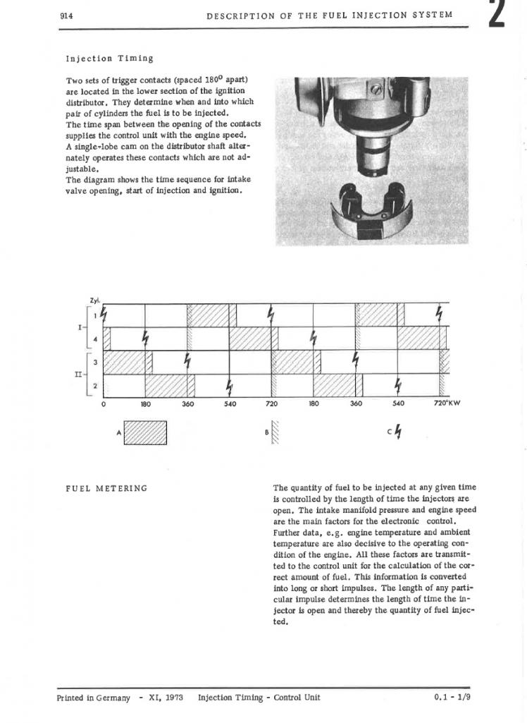
|
|
|
|
| 914_teener |
Jul 16 2020, 11:04 AM
Post
#12
|
|
914 Guru Group: Members Posts: 5,270 Joined: 31-August 08 From: So. Cal Member No.: 9,489 Region Association: Southern California |
QUOTE(Not_A_Six @ Jul 16 2020, 08:58 AM) QUOTE(914_teener @ Jul 16 2020, 08:22 AM) Added plus with the electronic dizzy is the elimination of the trigger points....and yes with regard to the cap and plug position. On the stock dizzy the vaccum can was in an awkward position and because the diaphram had failed and replacement parts my reasoning to use the 123. Good luck Thanks! Yeah, the 123 dizzy looks pretty sweet. It did force me to choose between vac advance and vac retard, though, as it doesn't have the ability to do both like the OEM one. (I chose vac retard -- profile 'A' -- as otherwise the timing was too advanced at idle to get the idle speed down.) Cheers. (IMG:style_emoticons/default/beerchug.gif) ??? Should be using ported vaccum for the advance and no retard or manifold vacuum. I.m wary of your post. |
|
|
|
| Not_A_Six |
Jul 16 2020, 11:44 AM
Post
#13
|
|
Member Group: Members Posts: 110 Joined: 28-November 18 From: North Idaho Member No.: 22,682 Region Association: Pacific Northwest |
QUOTE(JeffBowlsby @ Jul 16 2020, 09:38 AM) The trigger points contain 2 switches which each initiate an injection pulse 180 degrees dizzy rotation apart, each switch firing a bank of two paired injectors. Sure. On a '73 2.0 d-jet 914, the pulses are the "B" ones in that diagram. One pulse per cylinder per 720-degree I-C-P-E cycle. (with 180 degrees of dizzy rotation corresponding to 360 degrees of crank rotation.) Do you agree? Thanks. |
|
|
|
| GregAmy |
Jul 16 2020, 12:02 PM
Post
#14
|
|
Advanced Member Group: Members Posts: 2,677 Joined: 22-February 13 From: Middletown CT Member No.: 15,565 Region Association: North East States |
Bosch D-Jetronic is "batch injection".
Edit: look at the attached file, traces AA-AB, 5-10, upper right corner. Injectors are batched together and two are fired simultaneously. "Batch injection". 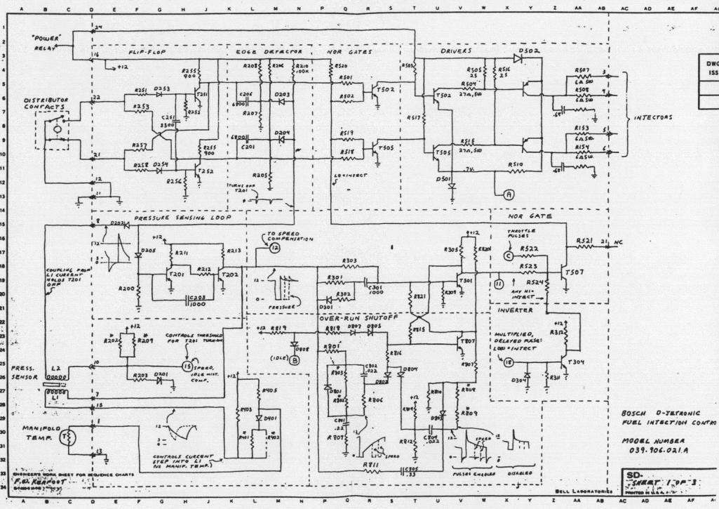 |
|
|
|
| Not_A_Six |
Jul 16 2020, 12:16 PM
Post
#15
|
|
Member Group: Members Posts: 110 Joined: 28-November 18 From: North Idaho Member No.: 22,682 Region Association: Pacific Northwest |
QUOTE(914_teener @ Jul 16 2020, 10:04 AM) QUOTE(Not_A_Six @ Jul 16 2020, 08:58 AM) Thanks! Yeah, the 123 dizzy looks pretty sweet. It did force me to choose between vac advance and vac retard, though, as it doesn't have the ability to do both like the OEM one. (I chose vac retard -- profile 'A' -- as otherwise the timing was too advanced at idle to get the idle speed down.) Cheers. (IMG:style_emoticons/default/beerchug.gif) ??? Should be using ported vaccum for the advance and no retard or manifold vacuum. I.m wary of your post. On a '73 2.0 d-jet 914, the throttle body has two vac ports -- one for advance at low load, and one for idle retard. (See ports "A" and "B" on the diagram below.) The OEM dizzy (039 905 205) also has two corresponding nipples. The 123 dizzy has a single vac port that can be used either for vac advance (e.g., profile "1") *or* vac retard (e.g., profile "A"). You have to choose. With profile #1, setting the centrifugal advance to give 27 degrees total (w/ vac hose plugged off) at 3500 rpm gives you an total advance of 5 degrees at idle. I couldn't get my idle speed below 1500 rpm with that much advance, even with the idle screw on the throttle body full clockwise. (Granted a vacuum leak could theoretically be the root cause of the high idle, but I've checked/replaced virtually *everything* and am 99% sure that I don't have a vac leak.) Using profile "A", there is no vacuum advance, but with the throttle plate closed at idle, there is enough retard at idle to get the idle speed to ~1000 rpm. This should (hopefully) mimic the total advance/retard of the OEM dizzy at idle. If I'm missing something, or have screwed up somehow, please help. (IMG:style_emoticons/default/confused24.gif) Thanks.  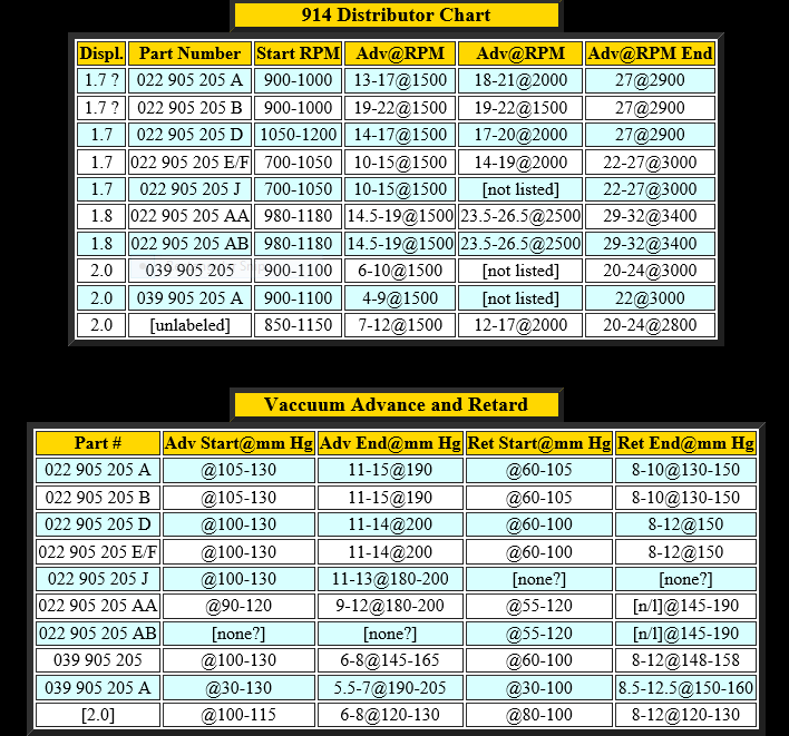 |
|
|
|
| Not_A_Six |
Jul 16 2020, 12:20 PM
Post
#16
|
|
Member Group: Members Posts: 110 Joined: 28-November 18 From: North Idaho Member No.: 22,682 Region Association: Pacific Northwest |
QUOTE(GregAmy @ Jul 16 2020, 11:02 AM) Bosch D-Jetronic is "batch injection". Edit: look at the attached file, traces AA-AB, 5-10, upper right corner. Injectors are batched together and two are fired simultaneously. "Batch injection". Thanks! That's consistent with my analysis. On the upper right of the schematic: Pin 3 controls injector for cylinder 1 Pin 4 controls injector for cylinder 4 Pin 5 controls injector for cylinder 3 Pin 6 controls injector for cylinder 2 (Though I may have pins 5 and 6 reversed...) Cheers. |
|
|
|
| 914_teener |
Jul 16 2020, 05:54 PM
Post
#17
|
|
914 Guru Group: Members Posts: 5,270 Joined: 31-August 08 From: So. Cal Member No.: 9,489 Region Association: Southern California |
QUOTE(Not_A_Six @ Jul 16 2020, 11:16 AM) QUOTE(914_teener @ Jul 16 2020, 10:04 AM) QUOTE(Not_A_Six @ Jul 16 2020, 08:58 AM) Thanks! Yeah, the 123 dizzy looks pretty sweet. It did force me to choose between vac advance and vac retard, though, as it doesn't have the ability to do both like the OEM one. (I chose vac retard -- profile 'A' -- as otherwise the timing was too advanced at idle to get the idle speed down.) Cheers. (IMG:style_emoticons/default/beerchug.gif) ??? Should be using ported vaccum for the advance and no retard or manifold vacuum. I.m wary of your post. On a '73 2.0 d-jet 914, the throttle body has two vac ports -- one for advance at low load, and one for idle retard. (See ports "A" and "B" on the diagram below.) The OEM dizzy (039 905 205) also has two corresponding nipples. The 123 dizzy has a single vac port that can be used either for vac advance (e.g., profile "1") *or* vac retard (e.g., profile "A"). You have to choose. With profile #1, setting the centrifugal advance to give 27 degrees total (w/ vac hose plugged off) at 3500 rpm gives you an total advance of 5 degrees at idle. I couldn't get my idle speed below 1500 rpm with that much advance, even with the idle screw on the throttle body full clockwise. (Granted a vacuum leak could theoretically be the root cause of the high idle, but I've checked/replaced virtually *everything* and am 99% sure that I don't have a vac leak.) Using profile "A", there is no vacuum advance, but with the throttle plate closed at idle, there is enough retard at idle to get the idle speed to ~1000 rpm. This should (hopefully) mimic the total advance/retard of the OEM dizzy at idle. If I'm missing something, or have screwed up somehow, please help. (IMG:style_emoticons/default/confused24.gif) Thanks. Yes....I believe you are missing something. First.....I.ll assume that you have the -4-R-V-IE. If this is the case then the advance curves are set by a small dip switch. The 123 curve for each motor and or distributor is listed on their website or in the little book that comes with the dizzy. Don.t know why you are posting the curves for the old dizzy numbers cause they are cross referenced by the 123 matrix to match the advance profile. Second....I.ll assume you have a stock cam. If not that can cause the high idle. Lastly post a pic for which vaccum port you used on the TB...or confirm from the cross section. If all of the above is correct then you idle mixture is wrong...the static timing is off....or most likely...you have a vacuum leak. |
|
|
|
| Not_A_Six |
Jul 16 2020, 06:54 PM
Post
#18
|
|
Member Group: Members Posts: 110 Joined: 28-November 18 From: North Idaho Member No.: 22,682 Region Association: Pacific Northwest |
QUOTE(914_teener @ Jul 16 2020, 04:54 PM) Yes....I believe you are missing something. First.....I.ll assume that you have the -4-R-V-IE. If this is the case then the advance curves are set by a small dip switch. The 123 curve for each motor and or distributor is listed on their website or in the little book that comes with the dizzy. Don.t know why you are posting the curves for the old dizzy numbers cause they are cross referenced by the 123 matrix to match the advance profile. Second....I.ll assume you have a stock cam. If not that can cause the high idle. Lastly post a pic for which vaccum port you used on the TB...or confirm from the cross section. If all of the above is correct then you idle mixture is wrong...the static timing is off....or most likely...you have a vacuum leak. Yep. -4-R-V-IE, with preset profiles set with the rotary DIP switch. I currently have the retard port on the throttle body (connection "2" or "B" on the diagram on post #15) connected to the 123 dizzy. The 123 instructions list two different profiles for the 039 905 205 (AKA Bosch 0 231 174 009) distributor -- "1" with vac advance, and "A" with vac retard. I posted the original dizzy advance/retard chart to show the original values. From the line in the chart for the -205 dizzy, at idle there should be no (or at least negligible) centrifugal advance, no vac advance (the advance port is "disabled" by the closed throttle plate), and about -10 degrees of vac retard. Under these conditions, a factory advance setting of +27 degrees at 3500 rpm on the original distributor corresponds to a net -5 degree retard at 1000 rpm idle w/ throttle plate closed. I believe that I've reproduced that with the 123 "A" profile and vac retard. Thanks for your help. Much appreciated. |
|
|
|
| rjames |
Jul 16 2020, 07:38 PM
Post
#19
|
|
I'm made of metal Group: Members Posts: 4,455 Joined: 24-July 05 From: Shoreline, WA Member No.: 4,467 Region Association: Pacific Northwest |
I have a 123dizzy and wasn’t able to get idle rpms below 1000 using either the advance of retard settings and at least one other person here had the same experience, IIRC. If you can’t get below 1500, something else is wrong. How was your idle before installing the 123?
Have you checked the throttle body air bleed screw? Sounds like a vacuum leak or timing is off. |
|
|
|
| Not_A_Six |
Jul 16 2020, 07:46 PM
Post
#20
|
|
Member Group: Members Posts: 110 Joined: 28-November 18 From: North Idaho Member No.: 22,682 Region Association: Pacific Northwest |
QUOTE(rjames @ Jul 16 2020, 06:38 PM) I have a 123dizzy and wasn’t able to get idle rpms below 1000 using either the advance of retard settings and at least one other person here had the same experience. That said, if you can’t get below 1500, something else is wrong. How was your idle before installing the 123? Have you checked the throttle body air bleed screw? Sounds like a vacuum leak or timing is off. Thanks for your comment. The whole idle/retard discussion is kind of tangential to the original FI phasing questions that I started the thread for. Nevertheless, it's interesting, and may be helpful to somebody else down the road. I *can* get it to idle just fine at around 1000 rpm with the 123 vac retard connected and profile "A". With profile "1", I couldn't get it below 1500 rpm. I figure that under idle conditions (no centrifugal advance, throttle plate closed) that profile "A" gives a net idle timing of -5 degrees (which matches OEM) and profile "1" gives a net timing of +5 degrees. I attribute the elevated idle with profile "1" to that difference in timing. But, I don't rule out that something else may be in play (e.g. an undetected vacuum leak as has been mentioned.) FWIW, this is not a stock engine. It's a 2056 with a webcam 73 cam. But, I don't believe this is the primary cause of the high idle with the vac advance profile. Cheers. (IMG:style_emoticons/default/beerchug.gif) |
|
|
|
|
1 User(s) are reading this topic (1 Guests and 0 Anonymous Users)
0 Members:

|
Lo-Fi Version | Time is now: 13th June 2026 - 01:41 AM |
Invision Power Board
v9.1.4 © 2026 IPS, Inc.