|
|
|
Porsche, and the Porsche crest are registered trademarks of Dr. Ing. h.c. F. Porsche AG.
This site is not affiliated with Porsche in any way. Its only purpose is to provide an online forum for car enthusiasts. All other trademarks are property of their respective owners. |
|
|

  |

| ss6 |
 Oct 1 2003, 03:17 PM Oct 1 2003, 03:17 PM
Post
#1
|
|
fun city...  Group: Members Posts: 261 Joined: 2-February 03 From: Western Connecticut Member No.: 221 |
There have been a number of threads here and elsewhere ranting about 914 speedo error, cable issues, tranny pick-off issues, etc, etc. I had my own speedo crisis recently, and I decided to bail on the whole ancient mechanical kluge. Thought I’d describe what I did in case any of you guys are in the same boat, and are looking for an alternative.
My speedo cable snapped a couple of weeks ago after I rotated the gauge in its mount for better view through a Momo steering wheel. I had an electronic 911 speedo (mine was from an ’84 Carrera) and found that it fits in the 914 gauge cluster perfectly. An electronic speedo is essentially just an electronic tach with a different dial face and a sender that transmits wheel (rather than crank shaft) revs. What stands out compared to the 914 mechanical speedo is the 911’s electronic speedo has an adjustment pot inside it that allows (relatively) easy recalibration if you’ve changed your tire size. There are threads on the Pelican 911 BBS that cover calibration, so I won’t cover those details here. The primary challenge was to cook up an appropriate “sender”, something I unwittingly had already done for a previous track video data project. (IMG:http://www.914world.com/bbs2/uploads/post-2-1065087044.jpg) Just like the mechanical speedo, the stock “sender” for the e-speedo is built into the tranny. In the 915 at least, there are 8 little magnets embedded at equal intervals in the ring gear. A reed switch on the outside of the tranny case is “tweaked” every time one of the magnets pass by, generating a stream of “switch closure” pulses which the electronic speedo converts to a speed readout. Home Made Wheel Speed Sensor My approach to fabricate a sender was to use a commercial proximity sensor to “watch” 8 metal “flags” clamped to an inboard CV joint (the flags are the yellow things in the pix). The flags are just ½” cutoffs of Home Depot ¾” galvanized angle, clamped to the CV with a large hose clamp. The flags rotate past the proximity sensor, causing the sensor to generate the pulse stream for the speedo. You’ll have to fab a bracket, and mount it to a convenient stud on the tranny case. I located mine as high up as I could to minimize road crud exposure. The whole assembly is shown below. I used 1” strap iron for the bracket shown, the sensor requires a ½” hole. (IMG:http://www.914world.com/bbs2/uploads/post-2-1065087133.jpg) I used a Cherry Corp gear tooth sensor, model number GS100701 which I got from DigiKey (www.digikey.com) for ~ $30 (the Porsche sensor is over twice the cost, naturally). (Digikey’s part number for this item is CH398-ND). This is a common sensor and is available from multiple distributors. It’s important to get the flags spaced evenly around the circumference of the CV joint, and to “fly” close to the sensor tip. You can make a flag spacing template by wrapping a skinny strip of paper around the CV body, marking where it overlaps, then folding the strip in half (with the mark lined up with the edge), then folding it in half twice more. Mark the creases, re-wrap on the CV, and transfer the marks. Clamp the flags loosely on the CV with the pipe clamp, line them up on the spacing marks, then slowly rotate the CV and make sure each flag “flies” past the sensor closely but without whacking the sensor. The surface of the flag should be parallel to the surface of the sensor tip. You can “calibrate” the distance by sandwiching a dime in between the sensor and the flag(s), then removing the dime without disturbing the flag. Tighten the hose clamp when everything is lined up. While the addition of the e-speedo is recent, this sensor rig has been on my car and trouble free for over a year now, with multiple DE’s and AX’s under its belt, not to mention at least one ice/salt/sand/ storm. Electrical Hookup You will have to splice enough extension wire onto the three 36” leads coming out of the sensor to get from the tranny all the way up to the speedo. Make sure to route the wiring away from the exhaust system and away from moving parts, and make sure the splices to extend the sensor leads are waterproof. I’d suggest using SAE-J1128 spec wire (try your local FLAPS that sells to the trade, or http://www.kayjayco.com/catP125CWire.htm, among other sources), 18 - 20 gauge is fine. The PVC cr@p that your low-end FLAPS sells won’t tolerate the oil and heat (or salt, or ice) very well. The sensor needs 12v and ground, and provides the direct output needed for the speedo. I terminated the leads with ¼” quick disconnects (Radio Shack), and used spade lug “doublers” (Radio Shack) to tap the switched 12v off the tach, and the ground wire that came up to the original speedo. You’ll also need to make a short jumper to bring 12v over from the back of your tach. The connections are as follows: - transfer the indicator lamp assemblies directly from the old speedo to the new speedo; - add a lug doubler between the tach’s 12v lug and its existing harness wire; - add a lug doubler to the speedo’s 12v lug; - the JUMPER wire you made goes from the 12v on the tach to the 12v on the speedo; - the BROWN wire from the sensor goes to the +12v lug doubler on the speedo; - add a lug doubler to the ground lug on the e-speedo; - the BROWN wire (from the orig. speedo) goes to the ground lug (-) on the e-speedo; - the BLACK wire from the sensor connects to the lug marked “31b” on the e-speedo; - the BLUE wire from the sensor goes to the (ground) lug doubler on the e-speedo; - the “A” lug on the electronic speedo is not used. (IMG:http://www.914world.com/bbs2/uploads/post-2-1065087070.jpg) My “new” speedo reads the same as the old one, ie its about 5mph high at 80 mph (on 205/55 - 16 tires). My sensor rig drives another (more accurate) system in addition to the e-speedo, so I’ve not bothered to fool around with recalibration. I believe (based on Pelican’s catalog) the electronic speedo’s from the 1976 - 1989 model years (911) should be usable, though speedo’s from a turbo might have a different calibration setting. The one I used came from a 1984 Carrera. Look for a speedo with individual lugs (as opposed to a single connector, which is probably from a C2); one of those lugs needs to be labeled “31b” (the DIN standard designation for a periodic-switch-closure-to-ground type of signal). |
   |

 
|
| ss6 |
Oct 1 2003, 03:25 PM
Post
#2
|
|
fun city... Group: Members Posts: 261 Joined: 2-February 03 From: Western Connecticut Member No.: 221 |
I *used* to be able to work a computer, can't seem to embed multiple pix in my post. Tried the "browse" thing at the bottom, but can only get one pic in.
|
|
|
|
| jtf914 |
Oct 1 2003, 03:27 PM
Post
#3
|
|
Member Group: Members Posts: 428 Joined: 31-December 02 From: Burlington, CT Member No.: 58 Region Association: North East States |
only 1 at a time here
|
|
|
|
| Air_Cooled_Nut |
Oct 1 2003, 04:25 PM
Post
#4
|
|
914 Ronin - 914 owner who lost his 914club.com Group: Members Posts: 1,748 Joined: 19-April 03 From: Beaverton, Oregon Member No.: 584 Region Association: None |
QUOTE(ss6 @ Oct 1 2003, 01:25 PM) I *used* to be able to work a computer, can't seem to embed multiple pix in my post. Tried the "browse" thing at the bottom, but can only get one pic in. So you use the IMG tag instead! [ I M G ] http://www... [ / I M G ] Of couse, you gotta have a web site that holds the images; you can't use your PC (unless it's a web server (IMG:style_emoticons/default/wink.gif) ). |
|
|
|
| Mueller |
Oct 1 2003, 04:47 PM
Post
#5
|
|
914 Freak! Group: Members Posts: 17,146 Joined: 4-January 03 From: Antioch, CA Member No.: 87 Region Association: None |
Neat....once you post all the pictures, this should be added to the "Classics" threads (IMG:style_emoticons/default/smilie_pokal.gif)
|
|
|
|
| ss6 |
Oct 1 2003, 10:24 PM
Post
#6
|
|
fun city... Group: Members Posts: 261 Joined: 2-February 03 From: Western Connecticut Member No.: 221 |
Mike, thanks for the attaboy. Got no website to hold the pix. The whole thing (with pix) is also on the Pelican BBS.
|
|
|
|
| 914Timo |
Oct 2 2003, 12:15 AM
Post
#7
|
|
******* Group: Members Posts: 743 Joined: 13-January 03 From: Finland Member No.: 137 Region Association: Europe |
Many thanks for all the details and instructions (IMG:style_emoticons/default/clap56.gif)
This is really cool setup. (IMG:style_emoticons/default/pray.gif) This is why I love internet and this site (IMG:style_emoticons/default/wub.gif) Many thanks. IMO this is the thread of the month and should be added to the "Classics" (IMG:style_emoticons/default/smilie_pokal.gif) |
|
|
|
| Jeff Bonanno |
Oct 2 2003, 02:01 AM
Post
#8
|
|
il dottore Group: Members Posts: 421 Joined: 30-April 03 From: San Diego, CA Member No.: 636 |
are you going to post the rest of the pics in this thread? very cool stuff.
|
|
|
|
| 914Timo |
Oct 2 2003, 03:30 AM
Post
#9
|
|
******* Group: Members Posts: 743 Joined: 13-January 03 From: Finland Member No.: 137 Region Association: Europe |
I can post the pics. I stole them from an other BBS (IMG:style_emoticons/default/wink.gif)
Attached image(s) 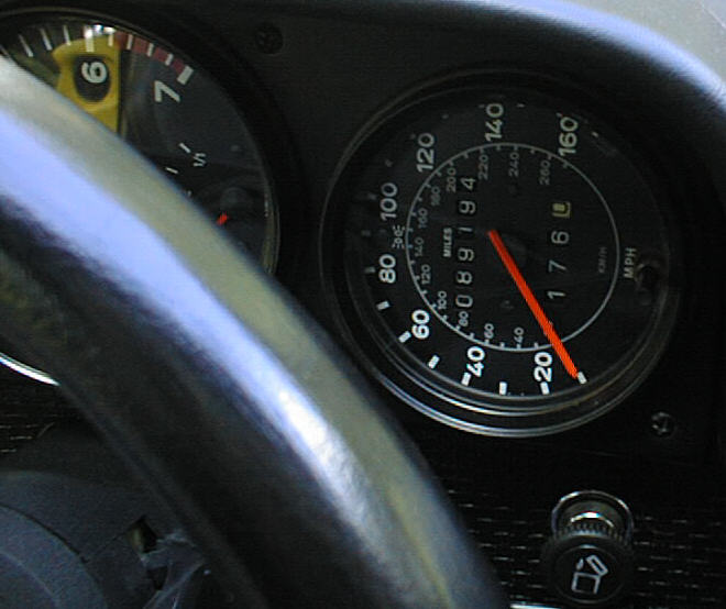
|
|
|
|
| 914Timo |
Oct 2 2003, 03:31 AM
Post
#10
|
|
******* Group: Members Posts: 743 Joined: 13-January 03 From: Finland Member No.: 137 Region Association: Europe |
2.00
Attached image(s) 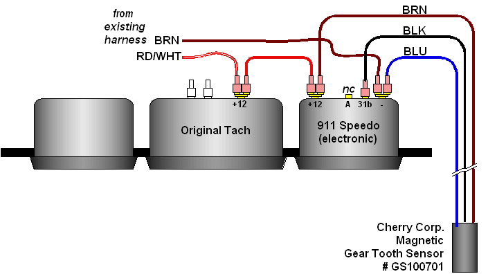
|
|
|
|
| 914Timo |
Oct 2 2003, 03:31 AM
Post
#11
|
|
******* Group: Members Posts: 743 Joined: 13-January 03 From: Finland Member No.: 137 Region Association: Europe |
3.00
Attached image(s) 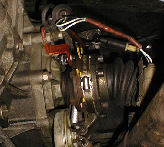
|
|
|
|
| 914Timo |
Oct 2 2003, 03:45 AM
Post
#12
|
|
******* Group: Members Posts: 743 Joined: 13-January 03 From: Finland Member No.: 137 Region Association: Europe |
I found some information about the sensor too.
Sorry John. I am not trying to steal this topic from you. You are the maestro here. I am just so excited about this (IMG:style_emoticons/default/laugh.gif) Attached thumbnail(s) 
|
|
|
|
| 914Timo |
Oct 2 2003, 03:46 AM
Post
#13
|
|
******* Group: Members Posts: 743 Joined: 13-January 03 From: Finland Member No.: 137 Region Association: Europe |
and the sensor.
Attached image(s) 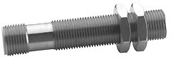
|
|
|
|
| ss6 |
Oct 2 2003, 05:18 AM
Post
#14
|
|
fun city... Group: Members Posts: 261 Joined: 2-February 03 From: Western Connecticut Member No.: 221 |
Guys, thanks for the attaboys. I've learned so much from this community, I thought it was time to give a little something back.
Timo, thanks for doing my work for me. Got a little frustrated with the pic thing, should have stuck with it a little longer. One minor point on the last sensor pic (directly above). That is a pic of a slightly different sensor in the same family as the one I used (Cherry's product literature isn't too clear), but a little too long to shoe-horn into the space required. The GS10701 is figure 1 in the Digikey page you posted. |
|
|
|
| fiid |
Oct 2 2003, 11:40 AM
Post
#15
|
|
Turbo Megasquirted Subaru Member Group: Members Posts: 2,827 Joined: 7-April 03 From: San Francisco, CA Member No.: 530 Region Association: Northern California |
Hey Mueller and other Eng people,
How hard would it be to make a plate with the teeth on it that gets sandwhiched in the cv joint?? Would need 4 bolt holes, 8 errr.... pokey out things. This plus the bracket and sensor would be an excellent kit!!! Fiid. |
|
|
|
| Mueller |
Oct 2 2003, 01:35 PM
Post
#16
|
|
914 Freak! Group: Members Posts: 17,146 Joined: 4-January 03 From: Antioch, CA Member No.: 87 Region Association: None |
It wouldn't be too hard to make a ring, or collar, it just comes down to interest and the most cost effective method.
A sheetmetal design wouldn't be too bad IMHO: Attached image(s) 
|
|
|
|
| ss6 |
Oct 2 2003, 03:48 PM
Post
#17
|
|
fun city... Group: Members Posts: 261 Joined: 2-February 03 From: Western Connecticut Member No.: 221 |
The collar approach is the way to go, you don't have to crack the CV joint to mount it. If I was sure up front that 8 was the right number of "flags" I needed, I would have tried to fab exactly what Mike has drawn. (Nice modelling pkg Mike, which one are you using???)
BTW, if you're going to go the hose clamp route, life will be a little easier if you use the spacing template I described in the post to mark the hose clamp instead of the CV joint, and tape the "flags" to the inside surface of the hose clamp prior to wrapping it around the CV joint. That way, they are less likely to fall out as you're assembling the, uh, assembly. |
|
|
|
| Red-Beard |
Oct 2 2003, 05:42 PM
Post
#18
|
|
"Ya canna change the laws of Physics" Group: Benefactors Posts: 1,124 Joined: 11-February 03 From: Houston, TX Member No.: 288 Region Association: None |
Mike - add 4 drilled tabs on the other side of the ring which would replace the lock tabs for the CV bolts. This way it is held on to the CV with the CV bolts. This will be much more secure and will prevent any possible rotation about the joint.
Keep the split arrangement so that it does not require removal of the CV for installation. Setup 2 of the tabs so that they are just on opposite sides of the split joint James |
|
|
|
| Red-Beard |
Oct 2 2003, 05:55 PM
Post
#19
|
|
"Ya canna change the laws of Physics" Group: Benefactors Posts: 1,124 Joined: 11-February 03 From: Houston, TX Member No.: 288 Region Association: None |
Picture
Attached image(s) 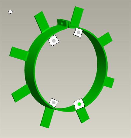
|
|
|
|
| Mueller |
Oct 2 2003, 06:16 PM
Post
#20
|
|
914 Freak! Group: Members Posts: 17,146 Joined: 4-January 03 From: Antioch, CA Member No.: 87 Region Association: None |
That would work James !!!!!
Pro/E is my tool of choice (IMG:style_emoticons/default/smile.gif) So easy even I can use it (IMG:style_emoticons/default/blink.gif) Attached image(s) 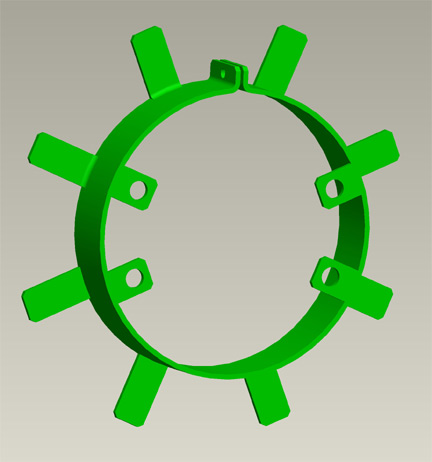
|
|
|
|
|
1 User(s) are reading this topic (1 Guests and 0 Anonymous Users)
0 Members:

|
Lo-Fi Version | Time is now: 12th May 2024 - 12:12 AM |
Invision Power Board
v9.1.4 © 2024 IPS, Inc.