Printable version of Entry
Click here to view this entry in its original format
URY914's Blog
New oil filler cover
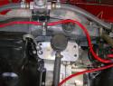
Last weekend during an a/x I had a problem with my oil filler cover coming off the “neck” of the engine case. I made the oil filler cover pictured below a few years ago because I didn’t like the stock tin one and wanted something with some bling. It never gave me a problem until last weekend but it did leak some oil once an awhile. The problem was the stock bale wire spring didn’t apply enough pressure on the gasket so give a good seal. I thought there must be something else I can do.
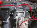
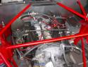
Picture of old filler cover on engine
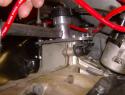
I figured if I could bolt a cover to the case, the bolts would tighten to apply pressure to the gasket. I looked at a spare engine I had and saw the two small 6mm case studs on the right side of the filler neck. All I needed to do is cut and fit a small steel angle to bolt on to those studs. I used a piece of 1/8” x 1” angle and cut/drilled it to fit. It also helped that Jake seemed to have changed these studs out to longer ones because the ones on the spare engine were much shorter. The studs were long enough to get the angle over them and have room for a lock washer and nut.
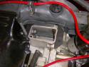
On the left side of the neck was not as easy as the right side. The dipstick was right next to the neck and there were no studs to use to attach the angle. The dipstick would mean the angle would be much shorter. On my engine Jake has drilled out the small hole where the bale wile spring attaches to the neck. He then installed a bolt with a hole drilled in the head of the bolt to receive the end of the bale wire. The intent I assume would be to spread the bale wire out therefore placing more pressure on the filler neck gasket. I decided to bolt the angle to the case using this hole.
I also welded the nuts to the bottom of the angles. The less parts to come loose the better.
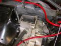
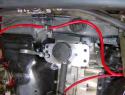
Picture of the case with no filler cover
Picture of the angles.
Picture of angles installed
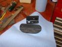
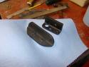
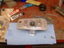
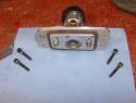
The new filler cover was made from a 1/4” piece of aluminum. I made it so it would cover the neck and by about 3/8” on the front and back sides and wide enough to be bolted to the angles. A hole was drilled for the dipstick. I used JB Weld to epoxy the filler funnel to the aluminum plate. The second picture below shows the gasket installed. A second piece of ¼” aluminum is used locate the cover on the neck and holds the gasket in place.
Pictures of the cover on the table.
I used socket head cap bolts because they look cool and dirt and engine grime doesn’t stick to them like hex head bolts.
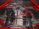
Pictures of cover installed.
I was able to get some shots from the bottom which show the gasket squeezed down tight on the case neck. I’ve adjusted the bolts from the time I took these pictures so that the gasket is tightened down as evenly as possible. The only problem is when I install the engine scoop, you can’t see this piece at all.
Attached thumbnail(s)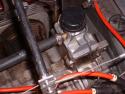

Powered by Invision Community Blog (http://www.invisionblog.com)
© Invision Power Services (http://www.invisionpower.com)