|
|
|
Porsche, and the Porsche crest are registered trademarks of Dr. Ing. h.c. F. Porsche AG.
This site is not affiliated with Porsche in any way. Its only purpose is to provide an online forum for car enthusiasts. All other trademarks are property of their respective owners. |
|
|

  |

| Spoke |
 Aug 15 2010, 10:54 AM Aug 15 2010, 10:54 AM
Post
#161
|
|
Jerry  Group: Members Posts: 7,279 Joined: 29-October 04 From: Allentown, PA Member No.: 3,031 Region Association: None |
While I'm in there: I'll paint the rear swaybar...
Attached image(s) 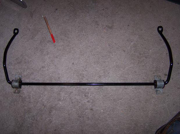
|
   |

 
|
| Spoke |
Aug 16 2010, 08:31 PM
Post
#162
|
|
Jerry Group: Members Posts: 7,279 Joined: 29-October 04 From: Allentown, PA Member No.: 3,031 Region Association: None |
Tunnel SS fuel lines in. Engine compartment SS fuel lines just sitting in place.
Attached image(s) 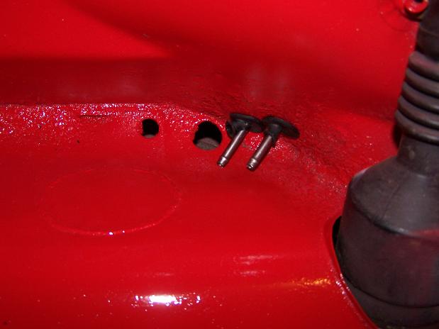 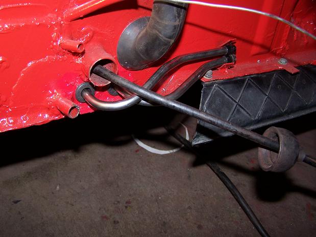 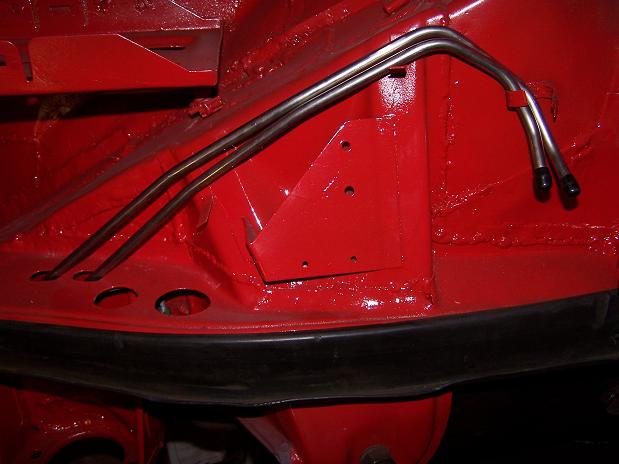
|
|
|
|
| Root_Werks |
Aug 17 2010, 01:16 PM
Post
#163
|
|
Village Idiot Group: Members Posts: 8,862 Joined: 25-May 04 From: About 5NM from Canada Member No.: 2,105 Region Association: Pacific Northwest |
This looks like another 914 saved from the rust monster!
Nice work, things are looking really solid again. (IMG:style_emoticons/default/welder.gif) |
 |
|
| Spoke |
Aug 19 2010, 10:59 PM
Post
#164
|
|
Jerry Group: Members Posts: 7,279 Joined: 29-October 04 From: Allentown, PA Member No.: 3,031 Region Association: None |
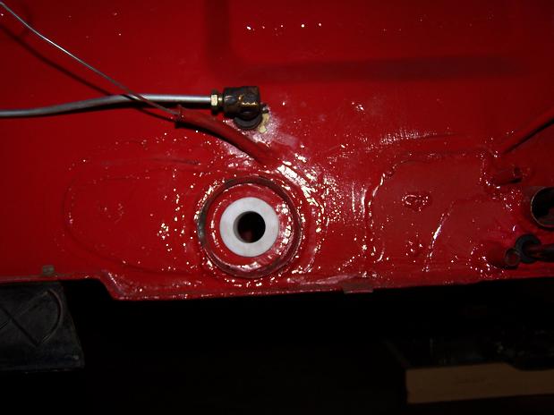
Fixing a hole in the vent.
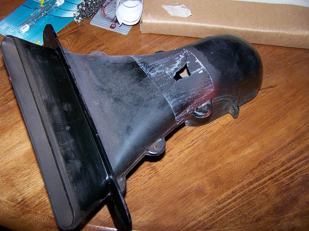 A little 22ga patch, a few rivets, and some silicon caulk and paint. 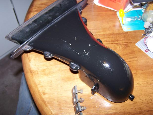 Cleaned up the securing bolts for the front flappers. 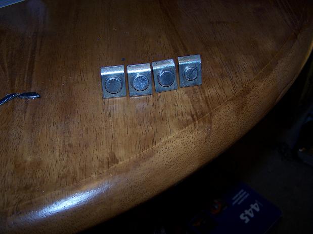 |
|
|
|
| Spoke |
Aug 20 2010, 04:38 AM
Post
#165
|
|
Jerry Group: Members Posts: 7,279 Joined: 29-October 04 From: Allentown, PA Member No.: 3,031 Region Association: None |
Fixing another hole this time in the fresh air fan where apparently in the previous life of this 914, the windshield wipers were run for a long time and the motor heated up and melted the outside of the fresh air fan.
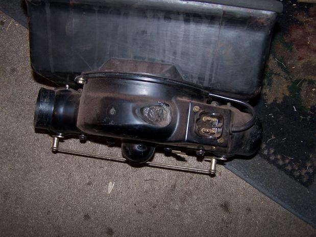 I didn't want to put a patch like on the flapper with rivets in case the rivets would interfere with the fan, so I got a piece of plastic and "welded" it in place with my 50 year old Craftsman solder gun. (IMG:style_emoticons/default/welder.gif) 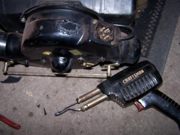 |
|
|
|
| Spoke |
Aug 20 2010, 07:15 AM
Post
#166
|
|
Jerry Group: Members Posts: 7,279 Joined: 29-October 04 From: Allentown, PA Member No.: 3,031 Region Association: None |
All of the air handling equipment is back in along with the windshield wiper assembly and windshield washer hoses.
I connected the battery to test the windshield wipers and fresh air fan. Good thing I did because I had connected the wipers wrong as I was viewing my wiring template 90 degrees off and all 4 wires (not ground) were one spade off. I'm almost back where I started in the front when I wanted to "pull the tank to put in SS fuel lines and locate the fuel pump up front" before the "while I'm in there" items got in the way: 1 Fix rust on both corners of the drip sill 2 Weld in the angle iron supports for the hood shocks 3 Weld in a bolt towards the interior for radio ground (was just a drilled hole + self-tapping screw). 4 Strip all the paint from the cowl and adjacent fender area 5 Weld-up fender-to-cowl gap 6 Remove all air handling equipment, windshield washer & wiper assembly 7 Remove hood cable release 8 Strip paint from entire tank compartment 9 Paint entire tank compartment, cowl, and adjacent fender area Things left to do up front: 1 Secure brake reservoir 2 re-install cowl braces 3 finish wiring for front fuel pump. Wires coiled right behind pedal assembly 4 mount fuel filter 5 plumb fuel lines 6 re-install tank 7 reinstall windshield washer reservoir Attached image(s) 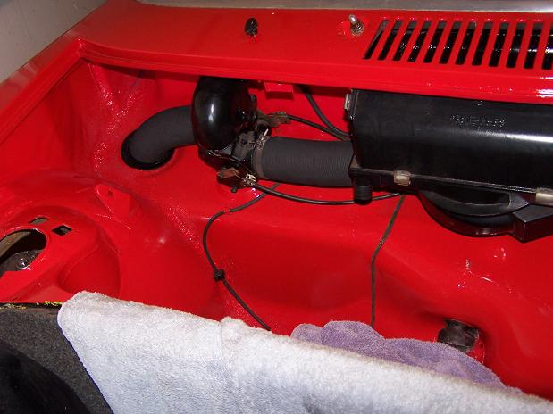 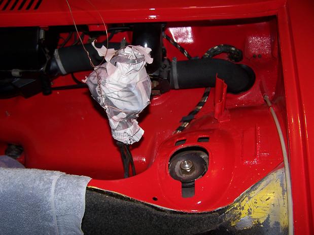
|
|
|
|
| Spoke |
Aug 21 2010, 04:35 PM
Post
#167
|
|
Jerry Group: Members Posts: 7,279 Joined: 29-October 04 From: Allentown, PA Member No.: 3,031 Region Association: None |
Turned the car around to get it in position for engine install.
Attached image(s) 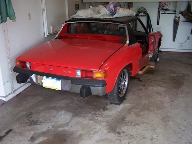
|
|
|
|
| Spoke |
Aug 21 2010, 04:43 PM
Post
#168
|
|
Jerry Group: Members Posts: 7,279 Joined: 29-October 04 From: Allentown, PA Member No.: 3,031 Region Association: None |
Got the firewall shift bushing in. Boiled the bushing in water in the microwave to warm it up. A couple of slugs with the hammer and it popped in.
 Installed new bushings into the coupler. 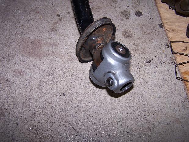 |
|
|
|
| Spoke |
Aug 21 2010, 04:48 PM
Post
#169
|
|
Jerry Group: Members Posts: 7,279 Joined: 29-October 04 From: Allentown, PA Member No.: 3,031 Region Association: None |
Before the engine goes in, there are a few things to tidy up:
1 Leaky pushrod tubes. Doing that now. 2 Install sideshift engine bar 3 Install alternator 4 Add 150 ohm resistor to HCT sender. It's resistance is a bit low. 5 Run engine before installing to check out all systems For now, changing leaky pushrod tubes. These ones came out of the driver side. Notice the chunks taken out of outside o-rings. No surprise of why these were leaking. And to think this engine was freshly rebuilt by GEX... 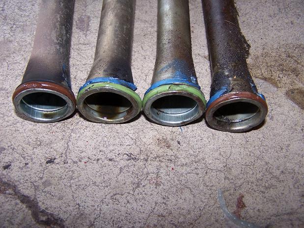 The inside o-rings look good but will be changed anyway. Why are there 2 colors for the o-rings? Different manufacturers? 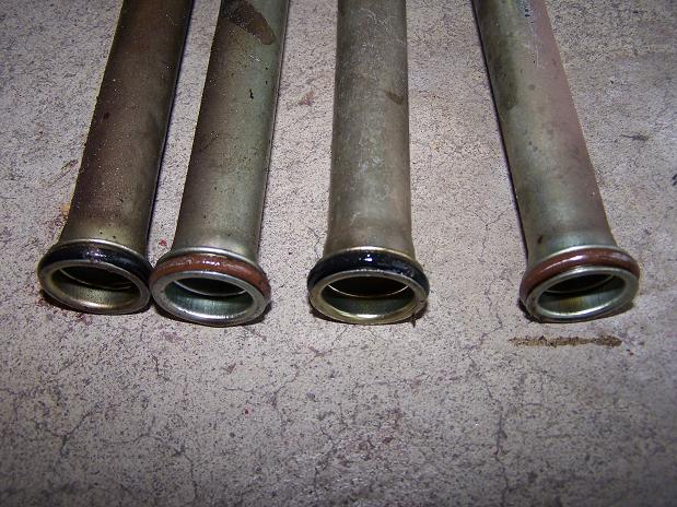 |
|
|
|
| Spoke |
Aug 22 2010, 01:13 AM
Post
#170
|
|
Jerry Group: Members Posts: 7,279 Joined: 29-October 04 From: Allentown, PA Member No.: 3,031 Region Association: None |
Not much left of this o-ring. There was plenty of gasket sealer on this tube but it still leaked. How shocking. (IMG:style_emoticons/default/mad.gif)
This nut looks like it had some sort of welding done to it or it is fractured in 2 places. No wonder I couldn't snug this one down... Attached thumbnail(s) 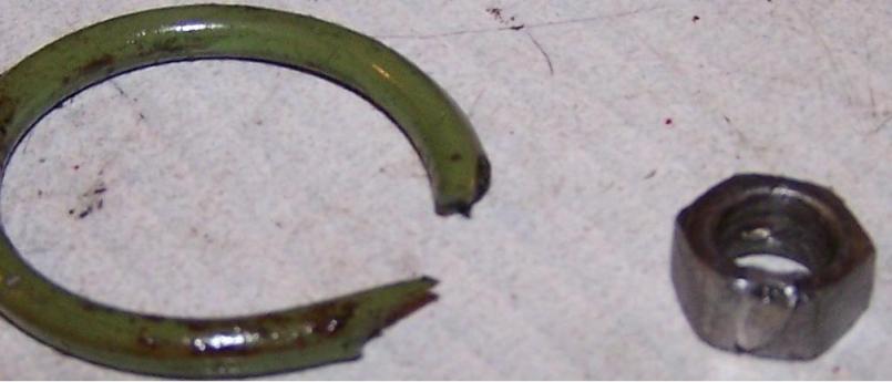
|
|
|
|
| Spoke |
Aug 22 2010, 06:51 PM
Post
#171
|
|
Jerry Group: Members Posts: 7,279 Joined: 29-October 04 From: Allentown, PA Member No.: 3,031 Region Association: None |
Got the pushrod tube o-rings put in and adjusted valves.
Finished plumbing the wires for the front mounted fuel pump. Went through the front firewall just above the boxed support. Attached image(s) 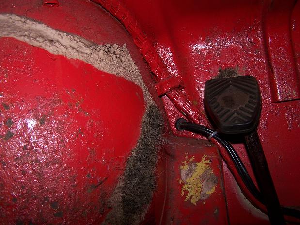 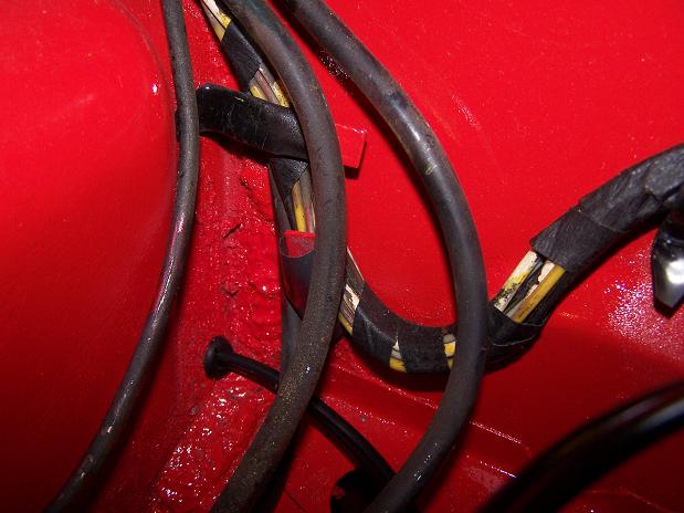
|
|
|
|
| Spoke |
Aug 22 2010, 06:52 PM
Post
#172
|
|
Jerry Group: Members Posts: 7,279 Joined: 29-October 04 From: Allentown, PA Member No.: 3,031 Region Association: None |
Tested the fuel pump relay by grounding pin III of the FI connector.
Got 12V at the front of the car for the fuel pump. (IMG:style_emoticons/default/beerchug.gif) This also means that the 12V for the FI brain is ok since it also drives the relay for the fuel pump. |
|
|
|
| Spoke |
Aug 22 2010, 07:02 PM
Post
#173
|
|
Jerry Group: Members Posts: 7,279 Joined: 29-October 04 From: Allentown, PA Member No.: 3,031 Region Association: None |
Before installing the engine, I would like to clean out the oil in the heat exchangers that has dripped from the pushrod tubes. There's a gooey oil mess on the inside bottom of the exchangers.
Any ideas of how to clean this out? I'm thinking some type of degreaser and then I'll have to somehow flush the inside of the exchanger with water or other solution. Attached image(s) 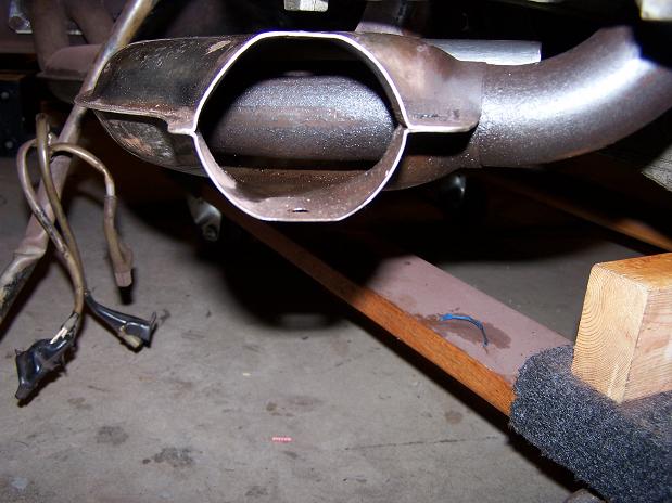
|
|
|
|
| Gigamight |
Aug 22 2010, 09:10 PM
Post
#174
|
|
Member Group: Members Posts: 220 Joined: 8-June 09 From: Near Akron, Ohio Member No.: 10,454 Region Association: Middle East |
I have no answer for you, but I am anxiously awaiting an answer to this question.
If anybody has a trick, please share it. |
|
|
|
| messix |
Aug 22 2010, 09:38 PM
Post
#175
|
|
AKA "CLUTCH KILLER"! Group: Members Posts: 6,995 Joined: 14-April 05 From: between shit kickers and pinky lifters/ puget sound wa.north of Seattle south of Canada Member No.: 3,931 Region Association: Pacific Northwest |
dish soap and a bottle brush
|
|
|
|
| Spoke |
Aug 23 2010, 07:06 AM
Post
#176
|
|
Jerry Group: Members Posts: 7,279 Joined: 29-October 04 From: Allentown, PA Member No.: 3,031 Region Association: None |
Getting the alternator back together. I needed to make the back panel gasket. To do this I used PowerPoint to make 2 concentric circles with 3 lines coming out at 120 degree increments for the bolt holes.
Attached image(s) 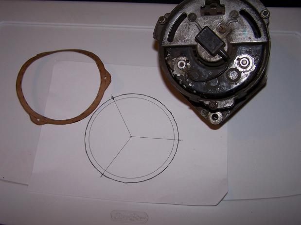
|
|
|
|
| jaxdream |
Aug 23 2010, 07:07 AM
Post
#177
|
|
Senior Member Group: Members Posts: 974 Joined: 8-July 08 From: North Central Tennessee Member No.: 9,270 Region Association: South East States |
Also might could try using some spray on / in oven cleaner. You could use the popular easy off , or get some other brand ( cheaper ) spray in both ends , tilt back and forth , let it run down inside , take to car wash to pressure spray out . I have used this method on the outside and works great , next is the inside . Good luck ...
Jack / Jaxdream |
|
|
|
| Spoke |
Aug 25 2010, 08:29 PM
Post
#178
|
|
Jerry Group: Members Posts: 7,279 Joined: 29-October 04 From: Allentown, PA Member No.: 3,031 Region Association: None |
Fabbed the fuel pump mounting tonight. I started with a rubber coupler from Home Depot with 2 hose clamps and cut the coupler so I had 2 pieces. The hose clamps will hold the pump in place and the coupler will provide some chassis buffering from the pump vibrations.
First order of business was to make 4 slots for the 2 hose clamps. My trusty Dremel tool with doubled cut-off wheels made just the right size slots for the clamps. 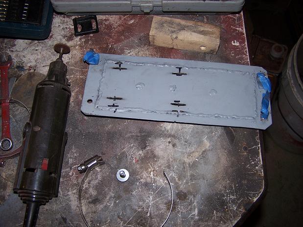 Looks like everything fits together real good. The pump was placed to one side of the door so that I can pull the pump out on one side followed by the other. If I centered the pump, I might have trouble bending the hose to clear the bulkhead. 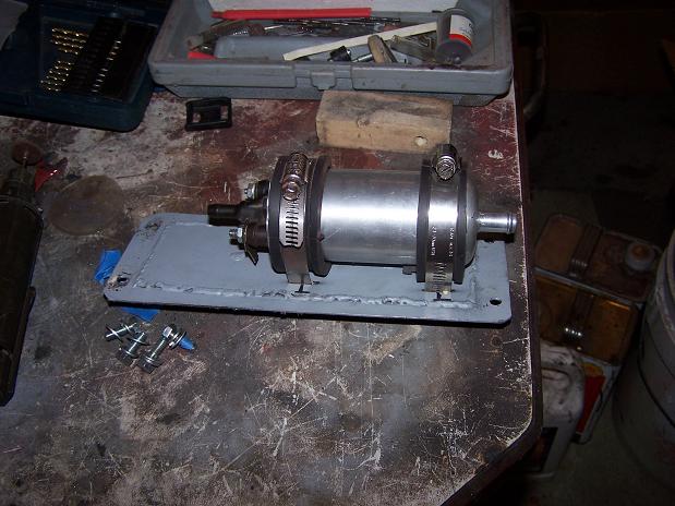 Placement in the tank compartment looks good. I couldn't use the standard pump mount since the pump would hit the brake lines. 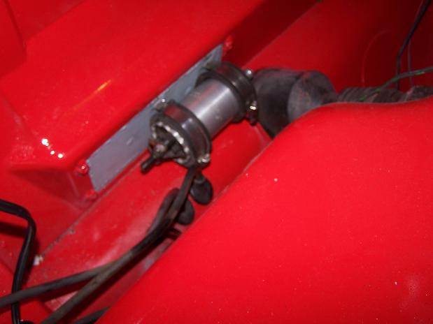 |
|
|
|
| Spoke |
Aug 28 2010, 11:19 AM
Post
#179
|
|
Jerry Group: Members Posts: 7,279 Joined: 29-October 04 From: Allentown, PA Member No.: 3,031 Region Association: None |
Pulled the tunnel fuel lines and bent them a little more to get some clearance for the hoses.
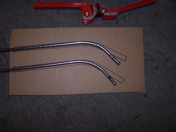 Just enough clearance to get the hoses on. 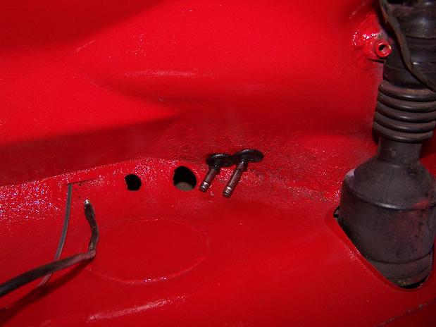 All the under-tank fuel hoses, fuel pump and filter are installed. I left enough hose to easily pull out the fuel pump and filter as well as be able to lift the tank out without disconnecting any lines. 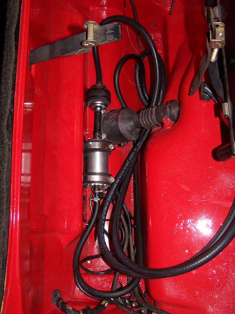 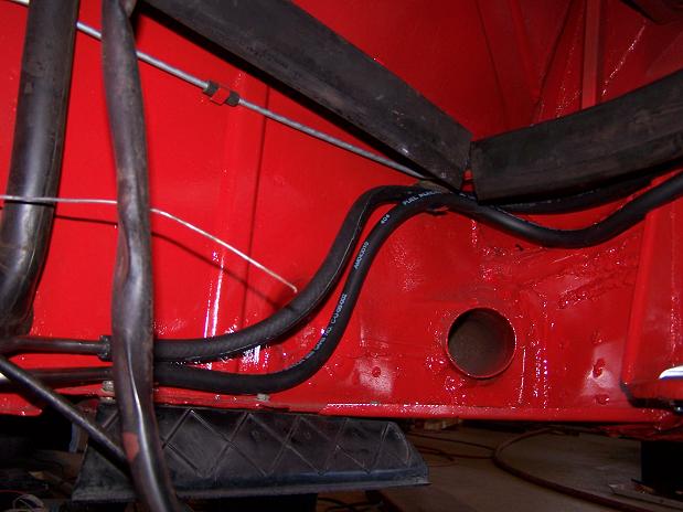 |
|
|
|
| Spoke |
Aug 28 2010, 11:40 AM
Post
#180
|
|
Jerry Group: Members Posts: 7,279 Joined: 29-October 04 From: Allentown, PA Member No.: 3,031 Region Association: None |
Fired up the engine before starting the install. I used the fuel system from the car to fire the engine. Also connected the battery to the starter using the car's starter cable.
The ground for the engine uses the cable that came with the engine for the starter cable. I connected the ground to the normal pigtail ground connection that goes to the tranny. I had to make very good connections as I am testing the alternator as well. Engine runs good, everything checks out. 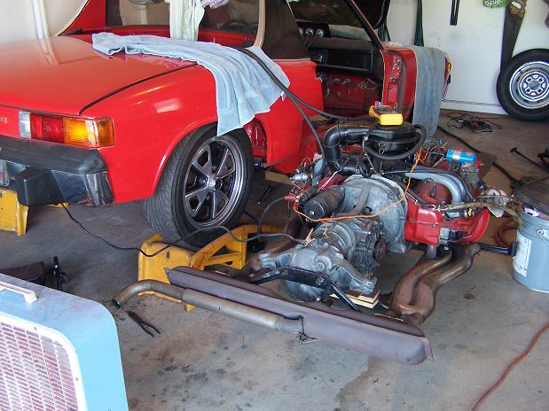 Fuel tank hoses are long enough to pull the tank without disconnecting the hoses. The fuel pump is running by shorting pin III to ground on the relay board. No leaks detected. Yea! 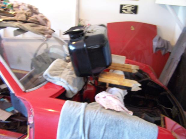 I tested the alternator by shorting D+ and B together then pulling them up to 12V through a resistor box. Got over 16V with the engine running so the alternator looks good. Time to install the engine. (IMG:style_emoticons/default/cheer.gif) 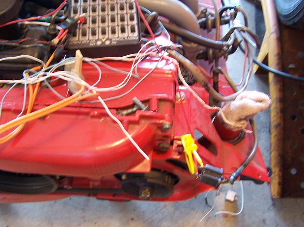 |
|
|
|
|
1 User(s) are reading this topic (1 Guests and 0 Anonymous Users)
0 Members:

|
Lo-Fi Version | Time is now: 8th December 2025 - 02:58 PM |
Invision Power Board
v9.1.4 © 2025 IPS, Inc.