|
|
|
Porsche, and the Porsche crest are registered trademarks of Dr. Ing. h.c. F. Porsche AG.
This site is not affiliated with Porsche in any way. Its only purpose is to provide an online forum for car enthusiasts. All other trademarks are property of their respective owners. |
|
|

  |

| ptravnic |
 Apr 27 2011, 03:05 PM Apr 27 2011, 03:05 PM
Post
#1
|
|
Senior Member  Group: Members Posts: 1,231 Joined: 27-May 03 From: Chicago, IL Member No.: 747 Region Association: None |
Hi all,
I have a 72 which does not have the nice U shaped blower motor mount in the engine compartment that the later years have. I'm operating under the impression that this bracket is the early stock mount for the motor assembly: 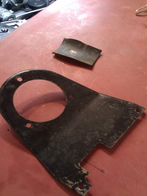 However, since the ground is supposed to be intermittent (actuates when the red cockpit lever is pulled up all the way) I have the problem where, because the above pictured mount grounds the entire assembly, I'm always grounded causing the blower to start up as soon as I turn on the ignition. I've tested my ground/red lever as the actuator when the motor assembly is not mounted (thus not automatically grounded) and it works like its supposed to - lever goes up and the motor turns on. Is there a way to separate the actual motor from the assembly so that it is not grounded when mounted? Maybe the rubber piece in the first pic goes somewhere that I'm obviously missing? 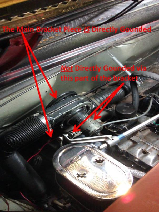 Is there another way to mount the motor assembly that I just don't know of? (IMG:style_emoticons/default/headbang.gif) (IMG:style_emoticons/default/hissyfit.gif) Thanks in advance! -pt ps - cross posted from the Club site. I'm staying out of the turf wars b/c I like folks on both boards... (IMG:style_emoticons/default/grouphug.gif) |
   |

 
|
| SirAndy |
Apr 27 2011, 03:14 PM
Post
#2
|
|
Resident German Group: Admin Posts: 41,669 Joined: 21-January 03 From: Oakland, Kalifornia Member No.: 179 Region Association: Northern California |
Never had an issues with that mount, motor and location. (IMG:style_emoticons/default/confused24.gif)
I had a 2-outlet blower mounted with that bracket. I used the two wires from the motor and hooked them up to the main harness. No extra rubber or spacers etc. Worked as expected, blower only came on when the red lever was pulled about half way up. Maybe your blower motor has a internal short? (IMG:style_emoticons/default/popcorn[1].gif) |
 |
|
| ptravnic |
Apr 27 2011, 03:23 PM
Post
#3
|
|
Senior Member Group: Members Posts: 1,231 Joined: 27-May 03 From: Chicago, IL Member No.: 747 Region Association: None |
QUOTE(SirAndy @ Apr 27 2011, 04:14 PM)  Never had an issues with that mount, motor and location. (IMG:style_emoticons/default/confused24.gif) I had a 2-outlet blower mounted with that bracket. I used the two wires from the motor and hooked them up to the main harness. No extra rubber or spacers etc. Worked as expected, blower only came on when the red lever was pulled about half way up. Maybe your blower motor has a internal short? (IMG:style_emoticons/default/popcorn[1].gif) I didn't think of that - just figured that the motor either works or it doesn't. (IMG:style_emoticons/default/confused24.gif) It is good to know that the mount is correct. (IMG:style_emoticons/default/beerchug.gif) -pt |
|
|
|
| ptravnic |
Apr 27 2011, 06:47 PM
Post
#4
|
|
Senior Member Group: Members Posts: 1,231 Joined: 27-May 03 From: Chicago, IL Member No.: 747 Region Association: None |
OK - so I think I have a workaround, although it doesn't appear to be consistent with the original setup.
The exploded parts diagram looks like this: 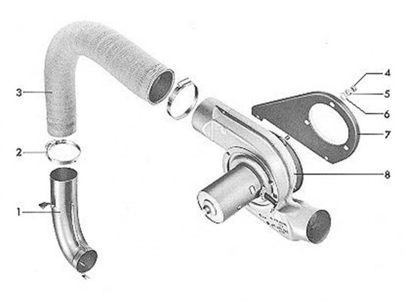 And my parts look like this: 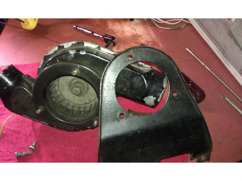 It seems like there should be something separating the metal in between # 7 (the bracket) & #8 (fan housing) in the exploded parts diagram. But alas, it is metal to metal so when the bracket gets mounted to the magnesium case, the entire setup gets grounded. So, to solve this dilemma I'm going to drill 3 larger holes in my #7 bracket and put a rubber grommet in there where the 3 threads push through. I'll also put a slightly larger rubber grommet on the base of the threads. That grommet will act as a large rubber washer since the base of the threads is slightly wider in diameter than the threads themselves. Hopefully there will be no metal from the bracket (which is grounded by attaching to the magnesium case) touching any metal or threads on the fan housing, thus making the fan and the housing ungrounded. Time to test my theory... (IMG:style_emoticons/default/smash.gif) -pt |
|
|
|
| Pat Garvey |
Apr 27 2011, 07:18 PM
Post
#5
|
|
Do I or don't I...........? Group: Members Posts: 5,899 Joined: 24-March 06 From: SE PA, near Philly Member No.: 5,765 Region Association: North East States |
QUOTE(ptravnic @ Apr 27 2011, 06:47 PM) OK - so I think I have a workaround, although it doesn't appear to be consistent with the original setup. It seems like there should be something separating the metal in between # 7 (the bracket) & #8 (fan housing) in the exploded parts diagram. But alas, it is metal to metal so when the bracket gets mounted to the magnesium case, the entire setup gets grounded. So, to solve this dilemma I'm going to drill 3 larger holes in my #7 bracket and put a rubber grommet in there where the 3 threads push through. I'll also put a slightly larger rubber grommet on the base of the threads. That grommet will act as a large rubber washer since the base of the threads is slightly wider in diameter than the threads themselves. Hopefully there will be no metal from the bracket (which is grounded by attaching to the magnesium case) touching any metal or threads on the fan housing, thus making the fan and the housing ungrounded. Time to test my theory... (IMG:style_emoticons/default/smash.gif) -pt There should be three rubber grommets to insulate. |
|
|
|
| euro911 |
Apr 27 2011, 11:15 PM
Post
#6
|
|
Retired & living the dream. God help me if I wake up! Group: Members Posts: 8,851 Joined: 2-December 06 From: So.Cal. & No.AZ (USA) Member No.: 7,300 Region Association: Southern California |
Hmmm (IMG:style_emoticons/default/idea.gif) ... is that why the fan on our '71 rattles so much?
Who sells replacement grommets? Regardless, I wouldn't think grounding the mounting bracket or fan housing would cause the fan to run continuously, grommets or not. The fan's power connector has a positive wire (green or yellow IIRC) and a ground wire (brown). Edit: Just performed an electrical check of the fans from our 1971 and our 1975. The VOM confirms that ground wires are the same potential as the housings (grounded). And both fan motors work. Porsches and VWs have some interesting electrical quirks. I don't remember exactly why, but I disconnected the heater fan wiring connections and apparently reconnected them wrong (reversed polarity). When I activated the heater lever, the ignition or injection system started missing (never did find out exactly which one). Luckily it was an easy fix, as the fan wiring connections was the only 'change' I had recently done to the car. Reconnected it correct polarity and everything was back to normal. (IMG:style_emoticons/default/driving.gif) |
|
|
|
| 914Mike |
Apr 28 2011, 12:03 AM
Post
#7
|
|
Member Group: Members Posts: 330 Joined: 27-January 03 From: San Jose, CA Member No.: 198 |
QUOTE(ptravnic @ Apr 27 2011, 02:05 PM) ... However, since the ground is supposed to be intermittent (actuates when the red cockpit lever is pulled up all the way) I have the problem where, because the above pictured mount grounds the entire assembly, I'm always grounded causing the blower to start up as soon as I turn on the ignition. I've tested my ground/red lever as the actuator when the motor assembly is not mounted (thus not automatically grounded) and it works like its supposed to - lever goes up and the motor turns on.... Your first assumption that the ground is supposed to switch the motor on is wrong. The ground from the heater switch goes to pin 9 of the front 14-pin connector on the relay board, which ends up at relay 54 pin 86. Pin 85 of the relay gets 12V from the key to power the relay whenever the ground from the switch arrives. The relay supplies +12V to the fan through the green wire to turn it on. The Brown wire from the fan motor goes directly to ground and should be grounded at all times. Relay #54 is the rearmost relay on the relay board. I've never had to isolate the motor housing from ground, in fact the diagram for a '71 shows the ground wire with a symbol that means the case itself is the ground, while the '73 diagram shows a wire going off the the ground point in front of the relay board. Either your motor has a short, or someone has done something to your relay. Or you are confusing the Green wire with ground, which is Brown on these cars. |
|
|
|
| Spoke |
Apr 28 2011, 07:28 AM
Post
#8
|
|
Jerry Group: Members Posts: 6,989 Joined: 29-October 04 From: Allentown, PA Member No.: 3,031 Region Association: None |
As Mike points out, the heater lever is a ground-based switch which energizes a relay on the relay board.
This relay provides 12V to the motor through the 25A fuse on the relay board. Check the voltages to ground of both wires to your fan with the fan disconnected. With the lever off, you should have zero volts on each one. With the lever on, you should have 12V on one, and zero volts on the other. Try this test and report back. Only the relay of interest is shown below in the schematic. Attached image(s) 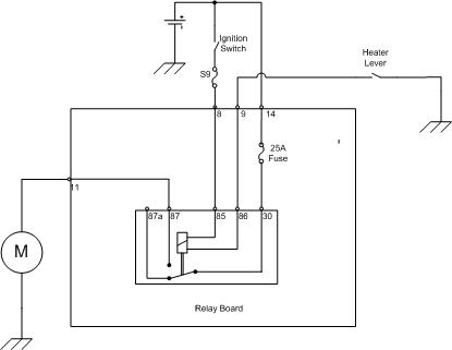
|
|
|
|
| ptravnic |
Apr 28 2011, 07:49 AM
Post
#9
|
|
Senior Member Group: Members Posts: 1,231 Joined: 27-May 03 From: Chicago, IL Member No.: 747 Region Association: None |
Looks like I'll be running some tests after work...
Thanks, gents. -pt |
|
|
|
| luskesq |
Apr 28 2011, 09:50 AM
Post
#10
|
|
Member Group: Members Posts: 276 Joined: 24-October 10 From: Fresno, CA Member No.: 12,303 Region Association: Central California |
I agree with what Mike914 said. I have the same setup and the bracket is not insulated from ground by rubber gromets or anything. Did you inspect the switch lever (or wiring to it) to make sure it isn't improperly grounded. My motor has two leads coming out of it, one for +, the other for -.
keith |
|
|
|
| Tom |
Apr 28 2011, 10:18 AM
Post
#11
|
|
Advanced Member Group: Members Posts: 2,139 Joined: 21-August 05 From: Port Orchard, WA 98367 Member No.: 4,626 Region Association: None |
Could be that you have an early blower motor with the internal ground. A previous owner may have purchased it to relace a defective blower and never got it working right? Or, as Andy says, you may have an internal short to case ground,
I just checked mine from a 76 and both wires are open to ground. Reading each wire to case ground = infinity ohms. Tom |
|
|
|
| ptravnic |
Apr 28 2011, 08:14 PM
Post
#12
|
|
Senior Member Group: Members Posts: 1,231 Joined: 27-May 03 From: Chicago, IL Member No.: 747 Region Association: None |
Electricity is out in the garage so no chance to dig into this tonight. Tomorrow...
|
|
|
|
| ptravnic |
Apr 29 2011, 12:26 PM
Post
#13
|
|
Senior Member Group: Members Posts: 1,231 Joined: 27-May 03 From: Chicago, IL Member No.: 747 Region Association: None |
On my lunch break - I did a couple tests. It turns out that I can't locate the wire going from the relay board to the heater motor. From the replies, I was able to determine that post 87 on the relay is the "switch" that turns on the positive juice to the motor. That switch is activated by the lever near the shifter in the cockpit.
Since I can't locate the proper wire coming out of the relay board, I wrapped wire around post 87 on the relay, put it back into the board, and connected the new wire to the heater blower motor positive wire. Now it works like it should. Pull the lever up, the relay activates, and the blower motor turns on. Now to figure a more eloquent way of running the wire from post 87... Mike & Spoke - I couldn't have done it without your posts. Digital High Five! (IMG:style_emoticons/default/aktion035.gif) -pt |
|
|
|
| SirAndy |
Apr 29 2011, 12:57 PM
Post
#14
|
|
Resident German Group: Admin Posts: 41,669 Joined: 21-January 03 From: Oakland, Kalifornia Member No.: 179 Region Association: Northern California |
QUOTE(ptravnic @ Apr 29 2011, 11:26 AM) Since I can't locate the proper wire coming out of the relay board On early cars, the wire is in the engine harness that is connected to the rear connector on the relay board. On later cars, the wire is in the main chassis harness and comes out of that under the relay board. On your '72, you should be able to find the wire on the rear connector and follow it through the engine harness ... (IMG:style_emoticons/default/bye1.gif) |
|
|
|
| SirAndy |
Apr 29 2011, 01:00 PM
Post
#15
|
|
Resident German Group: Admin Posts: 41,669 Joined: 21-January 03 From: Oakland, Kalifornia Member No.: 179 Region Association: Northern California |
Pin 11, green wire, going to (65) which is the heater blower. Ground should go to the chassis somewhere.
(IMG:http://www.914world.com/bbs2/uploads_offsite/www.pelicanparts.com-179-1304103637.1.jpg) (IMG:http://www.914world.com/bbs2/uploads_offsite/www.pelicanparts.com-179-1304103702.1.jpg) |
|
|
|
| ptravnic |
Apr 29 2011, 01:14 PM
Post
#16
|
|
Senior Member Group: Members Posts: 1,231 Joined: 27-May 03 From: Chicago, IL Member No.: 747 Region Association: None |
QUOTE(SirAndy @ Apr 29 2011, 02:00 PM) Pin 11, green wire, going to (65) which is the heater blower. Ground should go to the chassis somewhere. Andy, you are the man. See, it turns out that I just have a green jumper cable from one side of the loom to the other... No green wire heading out of the board! I wonder what that jumper cable was intended for? 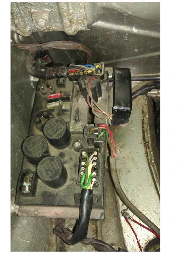 |
|
|
|
| SirAndy |
Apr 29 2011, 02:19 PM
Post
#17
|
|
Resident German Group: Admin Posts: 41,669 Joined: 21-January 03 From: Oakland, Kalifornia Member No.: 179 Region Association: Northern California |
QUOTE(ptravnic @ Apr 29 2011, 12:14 PM) I wonder what that jumper cable was intended for? I forget, but the jumper is supposed to be there (late only?) ... (IMG:style_emoticons/default/idea.gif) |
|
|
|
| SirAndy |
Apr 29 2011, 02:24 PM
Post
#18
|
|
Resident German Group: Admin Posts: 41,669 Joined: 21-January 03 From: Oakland, Kalifornia Member No.: 179 Region Association: Northern California |
Do you have the green wire in your engine harness at all? Maybe you have a late model chassis harness. What build date is your car? Is it early '72 or late '72?
In late '72, the wiring changed to this: (IMG:http://www.914world.com/bbs2/uploads_offsite/www.pelicanparts.com-179-1304108641.1.jpg) |
|
|
|
| SirAndy |
Apr 29 2011, 02:26 PM
Post
#19
|
|
Resident German Group: Admin Posts: 41,669 Joined: 21-January 03 From: Oakland, Kalifornia Member No.: 179 Region Association: Northern California |
Since you have the jumper, that implies you have a late model main harness. So, the green wire for the heater blower should come out pin 11 on the FRONT connector instead of the rear connector. Meaning, the stock plug for your blower motor comes out the main harness somewhere under the relay board.
(IMG:http://www.914world.com/bbs2/uploads_offsite/www.pelicanparts.com-179-1304108787.1.jpg) |
|
|
|
| SirAndy |
Apr 29 2011, 02:28 PM
Post
#20
|
|
Resident German Group: Admin Posts: 41,669 Joined: 21-January 03 From: Oakland, Kalifornia Member No.: 179 Region Association: Northern California |
QUOTE(ptravnic @ Apr 29 2011, 12:14 PM) Wait a minute! Your jumper is wrong! It should go from 11 to 10, not from 9 to 10 ... (IMG:style_emoticons/default/rolleyes.gif) |
|
|
|
|
1 User(s) are reading this topic (1 Guests and 0 Anonymous Users)
0 Members:

|
Lo-Fi Version | Time is now: 2nd June 2024 - 02:20 PM |
Invision Power Board
v9.1.4 © 2024 IPS, Inc.