|
|
|
Porsche, and the Porsche crest are registered trademarks of Dr. Ing. h.c. F. Porsche AG.
This site is not affiliated with Porsche in any way. Its only purpose is to provide an online forum for car enthusiasts. All other trademarks are property of their respective owners. |
|
|

  |

| HarveyH |
 Aug 23 2004, 08:48 AM Aug 23 2004, 08:48 AM
Post
#1
|
|
Member  Group: Members Posts: 450 Joined: 19-June 03 From: Downingtown, PA Member No.: 843 |
Every now and the, someone asks about modified distributor rotors for use with high energy ignitions. The higher voltage and current produced by high-energy ignition systems has been known to burn out the internal resistor in distributor rotors. Of course, these failures always seem to occur at the most inopportune times, so it’s a good idea to be ready. You can buy modified rotors from Aircooled.net for less than $20, or make your own if you’re feeling cheap. I seem to remember that a while back Aircooled.net had this process posted on their website, but I can’t find it. I’m cheap, and I’m also ready for an arts and crafts project, so I’m going to make up a couple and document the process.
Harvey Things you’ll need: Rotor, new or used. Since the primary failure of a rotor is in the internal resistor, if the tip and contact aren’t too badly burned, they can be polished up and re-used. Soldering iron, solder, and flux. #12 wire. AWG #12 wire is rated at 20 Amps, so that should be more than enough. Epoxy. Since there is no real structural use here, choice of an epoxy is not too critical. Generally, longer cure times tend to indicate higher bond strength and higher temperature ratings. Attached image(s) 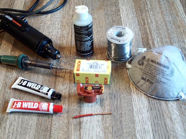
|
   |

 
|
| HarveyH |
Aug 23 2004, 08:50 AM
Post
#2
|
|
Member Group: Members Posts: 450 Joined: 19-June 03 From: Downingtown, PA Member No.: 843 |
Dust Mask. I’ve never noticed it before, but one of my two new Bosch rotors is from Germany, and the packaging contains an asbestos warning. The rotor from Spain does not contain the warning. Better safe than sorry… (IMG:style_emoticons/default/blink.gif)
Attached image(s) 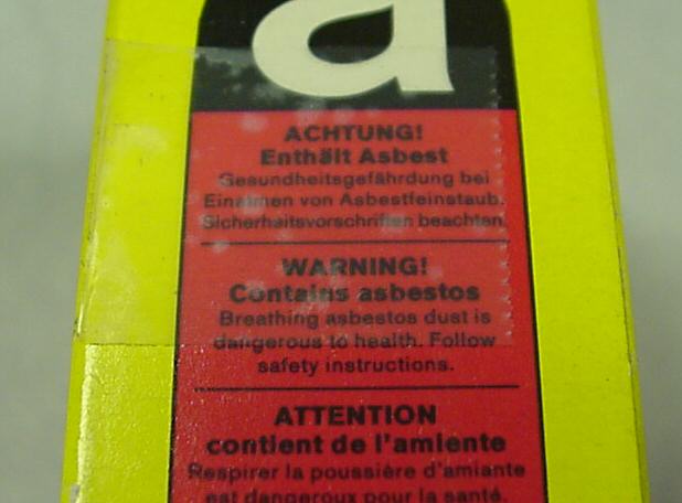
|
|
|
|
| HarveyH |
Aug 23 2004, 08:51 AM
Post
#3
|
|
Member Group: Members Posts: 450 Joined: 19-June 03 From: Downingtown, PA Member No.: 843 |
Dremel tool or die grinder with a small cutting burr.
Attached image(s) 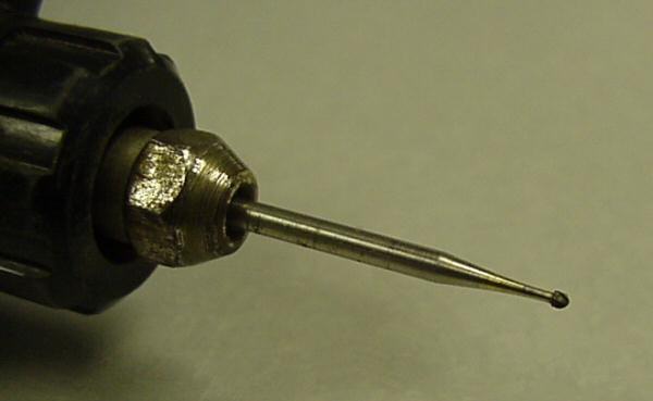
|
|
|
|
| HarveyH |
Aug 23 2004, 08:52 AM
Post
#4
|
|
Member Group: Members Posts: 450 Joined: 19-June 03 From: Downingtown, PA Member No.: 843 |
Wear your dust mask!
Use the Dremel with a small burr to cut the existing epoxy and the internal resistor out of the rotor. Leave the rotor tip and the center contact secured in the rotor, but clean out on both sides of the connection tabs. Attached image(s) 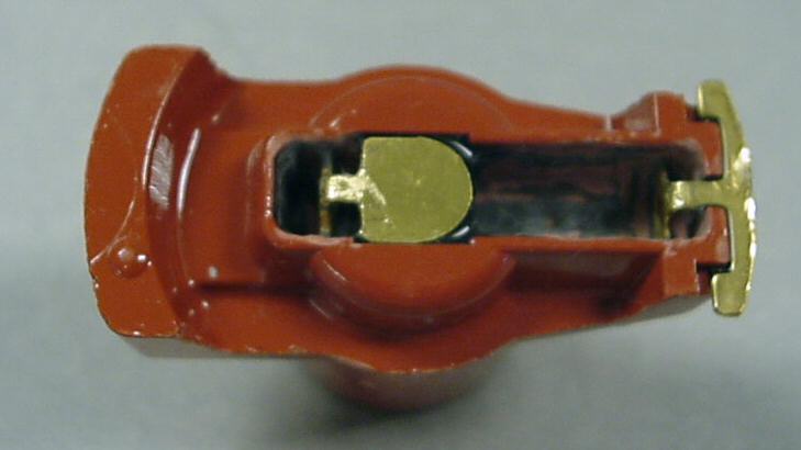
|
|
|
|
| HarveyH |
Aug 23 2004, 08:52 AM
Post
#5
|
|
Member Group: Members Posts: 450 Joined: 19-June 03 From: Downingtown, PA Member No.: 843 |
Run the cutting burr up under the center contact to cut a passage for the new wire, but leave the contact securely bonded to the rotor.
|
|
|
|
| HarveyH |
Aug 23 2004, 08:54 AM
Post
#6
|
|
Member Group: Members Posts: 450 Joined: 19-June 03 From: Downingtown, PA Member No.: 843 |
Forgot to post the picture (IMG:style_emoticons/default/confused24.gif)
Attached image(s) 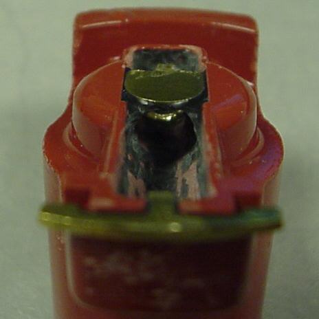
|
|
|
|
| HarveyH |
Aug 23 2004, 08:55 AM
Post
#7
|
|
Member Group: Members Posts: 450 Joined: 19-June 03 From: Downingtown, PA Member No.: 843 |
Gently run the cutting burr against the connection tabs to grind all of the epoxy off of the surfaces so that you can make a good solder connection to the brass. Clean up the dust, and flush out the rotor with Isopropyl alcohol or Acetone
Attached image(s) 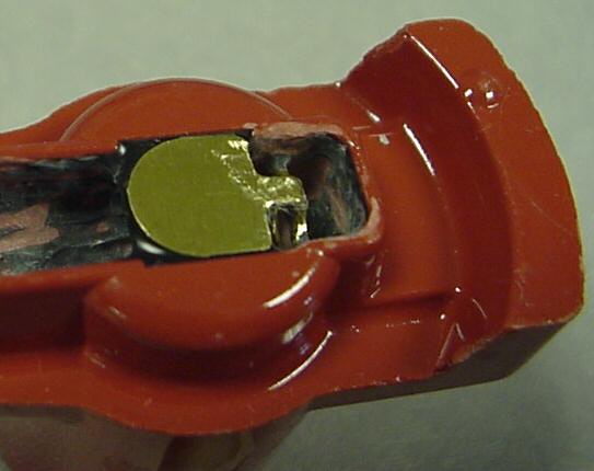
|
|
|
|
| HarveyH |
Aug 23 2004, 08:56 AM
Post
#8
|
|
Member Group: Members Posts: 450 Joined: 19-June 03 From: Downingtown, PA Member No.: 843 |
Strip the insulation off of about 1-1/2” of #12 stranded wire. Tin the wire and clean off any residual soldering flux.
A tip on soldering: Wipe the tip of the iron with a damp cloth or sponge to remove old, oxidized solder. Apply a small amount of fresh solder to the tip of the iron. Place the iron against your work. Allow the work to heat a few seconds and feed fresh solder onto the work piece allowing the work piece to melt the solder. Don’t apply solder directly onto the iron to make the connection. Remove the iron. Feed a small amount of fresh solder onto the tip to prevent the tip from oxidizing. Allow the work piece to cool. Clean any residual flux using Isopropyl alcohol or a commercial flux remover. The tinned wire is stiff, so you’ll have to carefully cut it to length. Slide it back under the center contact and through the hole in the center contact connection tab. Lower the front end of the wire and slide it forward into the hole in the rotor tip connection tab. There is no apparent stress relief in the original construction of the rotor, and the cavity was filled solidly with rigid epoxy, so I never really thought that stress relief bends were an issue in this assembly. Attached image(s) 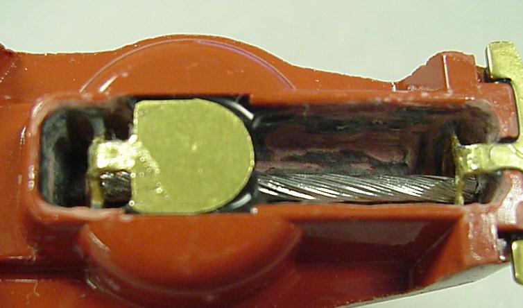
|
|
|
|
| HarveyH |
Aug 23 2004, 08:56 AM
Post
#9
|
|
Member Group: Members Posts: 450 Joined: 19-June 03 From: Downingtown, PA Member No.: 843 |
Put a little soldering flux on the connection tabs and solder the wire in place. Clean off any residual soldering flux. (Isopropyl alcohol, and/or Acetone is best since they will degrease the parts and leave no residue.
The major cause of failure in gluing or bonding is that the surfaces were not prepared properly. They must be absolutely clean!!! Make sure there are no grease or oil on the surfaces being bonded. Attached image(s) 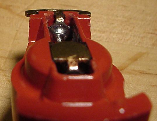
|
|
|
|
| HarveyH |
Aug 23 2004, 08:57 AM
Post
#10
|
|
Member Group: Members Posts: 450 Joined: 19-June 03 From: Downingtown, PA Member No.: 843 |
Mix the epoxy in accordance with the manufacturers instructions.
Fill the cavity in the Rotor with epoxy. Paste epoxies will require that you use a matchstick or a small piece of wood or wire to pack the epoxy into the cavity, forcing it back through the hole under the center contact. When the cavity is full, use a Q-Tip or a piece of cloth or paper towel wet with alcohol to wipe the epoxy off flush with the top of the rotor. Make sure you clean off the top of the center contact. Allow the epoxy to fully cure before proceeding. Heating is not really necessary, but it will speed the cure of the epoxy, normally 145 to 150 degrees F is sufficient. Heat curing will usually cause the epoxy to liquefy a bit as it heats and allow the epoxy to fill the cavity better, and may let any entrapped air rise out of the fill. DON’T use an over that you use for food! Attached image(s) 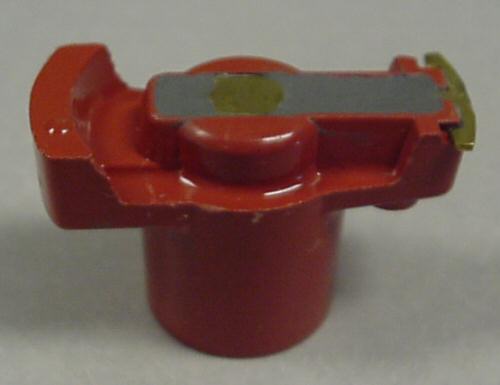
|
|
|
|
| HarveyH |
Aug 23 2004, 08:58 AM
Post
#11
|
|
Member Group: Members Posts: 450 Joined: 19-June 03 From: Downingtown, PA Member No.: 843 |
When the epoxy is fully cured, use a small piece of wet-or-dry paper to polish the top of the center contact to make sure there is no epoxy residue insulating the surface.
Install the rotor in your distributor and go for a drive. (IMG:style_emoticons/default/driving.gif) Harvey Attached image(s) 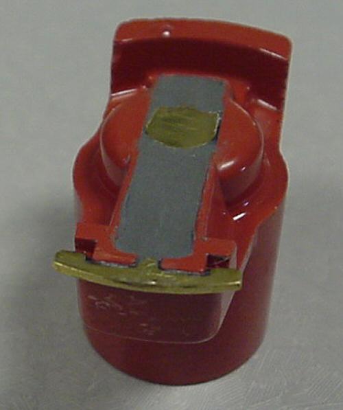
|
|
|
|
| McMark |
Aug 23 2004, 09:03 AM
Post
#12
|
|
914 Freak! Group: Retired Admin Posts: 20,180 Joined: 13-March 03 From: Grand Rapids, MI Member No.: 419 Region Association: None |
Great write-up. Thanks Harvey! (IMG:style_emoticons/default/smilie_pokal.gif)
|
|
|
|
|
1 User(s) are reading this topic (1 Guests and 0 Anonymous Users)
0 Members:

|
Lo-Fi Version | Time is now: 28th July 2026 - 12:34 AM |
Invision Power Board
v9.1.4 © 2026 IPS, Inc.