|
|
|
Porsche, and the Porsche crest are registered trademarks of Dr. Ing. h.c. F. Porsche AG.
This site is not affiliated with Porsche in any way. Its only purpose is to provide an online forum for car enthusiasts. All other trademarks are property of their respective owners. |
|
|

  |

| Tom |
 Oct 8 2014, 02:21 PM Oct 8 2014, 02:21 PM
Post
#1
|
|
Advanced Member  Group: Members Posts: 2,139 Joined: 21-August 05 From: Port Orchard, WA 98367 Member No.: 4,626 Region Association: None |
I have been reading up on some things that have grown dim in my mind over the years. While researching something else, I came across an eye-opener for me. Using equivalent circuits to understand what is happening in an electrical circuit that is failing or has failed. I had totally forgotten this technique. I tried it for the fog light circuit and in the process realized that many of our circuits are very similar. Like for the starter solenoid, just change the value of R1 to .9 ohms. As you can see, the connector resistance (key switch included) must be less that .9 ohms to even get 6 volts. So that means that the connectors need to be even cleaner and tighter. To clarify, if the connector resistance was 0.3 ohms and the solenoid resistance was 0.9 ohms, then the ratio of voltage across each resistance would be 25% across the connectors and 75% across the solenoid, resulting in 9 volts at the solenoid. To get the ratio, add the total resistance ( 0.3 = 0.9 ) = 1.2V and divide by the resistance of the solenoid. 0.9/1.2 = 75%. So 75% of the voltage reaches the solenoid. Just barely enough. If your 914 is at this point where the solenoid is working most of the time, just add some heat and it will stop. Heat increases resistance.
In the pics you will see the fog light circuit drawn as it is, ( well I may have missed a connection or two ), and then a simplified circuit showing the load resistance and connection resistance. As TABLE 1 shows, as the connectors start gaining resistance, the total circuit resistance increases, total circuit current decreases, and the power decreases, especially notice the power across the connector that is failing and the power across the load. As the connectors fail, the power goes down until there is almost no power or voltage being dropped across the load. A good circuit drops 12 volts, 75 watts across the load ( the fog lamps, starter, other electrical device ), as the connector deteriorates the load drops less and less and the connector draws all or almost all ) of the voltage. When the connector gets to 8 ohms resistance, the total circuit resistance is 10 ohms and the connector is dropping 8/10s of the 12 volts. I don't thing 2.4 volts across the fog lamps will light them at all. Another bad thing about power being developed across a connection is that they are not designed to handle heat. As Table 1 shows, at 2 ohms the load and connector share power at 18 watts each. If the failing connector is a relay socket, the heat has no where to go, so it just heat up until something melts, adding more resistance to the connection. Maybe some of our EE members can check over my musings and see if I am off base or maybe hit on a reoccurring issue for us. I know using this info, electrical trouble shooting will be easier. If one were to use pins and jumper clips across every connector in a circuit that is on but not working, the bad connector could be found quickly. Any one that reads voltage would be dropping that voltage and the load would be getting less voltage. Hope this will be of some help to our members, Tom EDIT: evidently there isn't much interest in this information. Over 190 looks and only 1 question from an interested member. Either no one is having issues or the information is too technical, even though I tried to simplify it as much as I could. Tom Attached thumbnail(s) 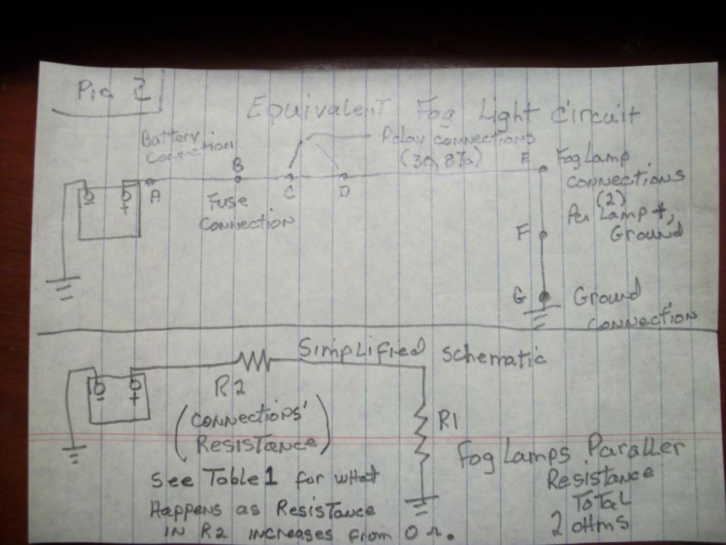 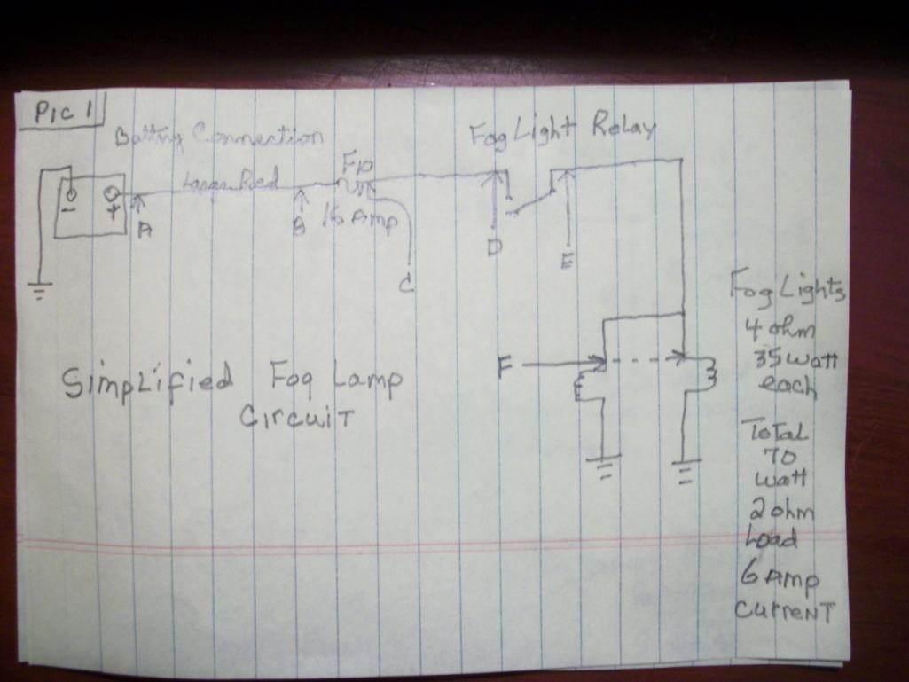 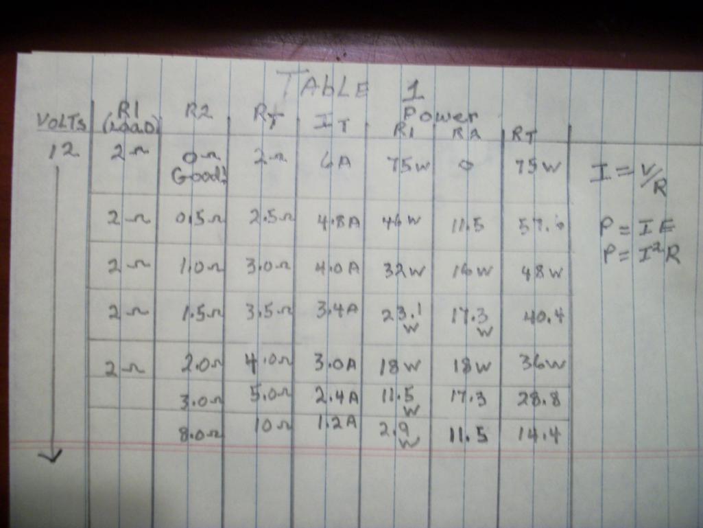
|
   |

 
|
| bandjoey |
Oct 8 2014, 04:00 PM
Post
#2
|
|
bandjoey Group: Members Posts: 4,934 Joined: 26-September 07 From: Bedford Tx Member No.: 8,156 Region Association: Southwest Region |
I don't have a clue what all this means but my fogs have always been dim. With new bulbs and cleaned sockets they're only decorative to me.
Y'all work this out and it will brighten my day. (IMG:style_emoticons/default/beerchug.gif) U R the wizard of electric power! |
|
|
|
| Tom |
Oct 8 2014, 06:58 PM
Post
#3
|
|
Advanced Member Group: Members Posts: 2,139 Joined: 21-August 05 From: Port Orchard, WA 98367 Member No.: 4,626 Region Association: None |
Bill,
I would start with the fog lamp relay and make sure the contacts in the socket are clean and the prongs are clean, A piece of fine sandpaper will do for this, wash them with alcohol and dry well. You can spread the prongs very slightly to ensure a better contact in the relay socket. Tom |
|
|
|
| bandjoey |
Oct 8 2014, 11:17 PM
Post
#4
|
|
bandjoey Group: Members Posts: 4,934 Joined: 26-September 07 From: Bedford Tx Member No.: 8,156 Region Association: Southwest Region |
Thanks. I'll try that. Cleaned the lamps but never looked at the relay.
|
|
|
|
| Tom |
Nov 4 2014, 03:56 AM
Post
#5
|
|
Advanced Member Group: Members Posts: 2,139 Joined: 21-August 05 From: Port Orchard, WA 98367 Member No.: 4,626 Region Association: None |
Bill,
Did you ever get around to cleaning your relay contacts? Did it make things better? Tom |
|
|
|
|
1 User(s) are reading this topic (1 Guests and 0 Anonymous Users)
0 Members:

|
Lo-Fi Version | Time is now: 2nd July 2025 - 08:28 PM |
Invision Power Board
v9.1.4 © 2025 IPS, Inc.