|
|
|
Porsche, and the Porsche crest are registered trademarks of Dr. Ing. h.c. F. Porsche AG.
This site is not affiliated with Porsche in any way. Its only purpose is to provide an online forum for car enthusiasts. All other trademarks are property of their respective owners. |
|
|

  |

| Marv's3.6six |
 May 4 2016, 08:03 PM May 4 2016, 08:03 PM
Post
#1
|
|
Actual member 7"  Group: Members Posts: 695 Joined: 22-November 04 From: Huntington Beach, Ca. Member No.: 3,165 Region Association: Southern California |
Hi guys. Are looking for some electric advice.....I have added 4 ea 4" SPAL puller fans to the back of my oil cooler. Currently I have these 4 fans on one circuit fused at 25 amps. I am told the fans individually draw 1.9 amps while running but will pull 4amps ea at start up. Are using a Bosch type relay to power the fans which is triggered by a thermal switch. I have a 4 position mini fuse block and have fabbed up part of the wiring harness.
My question is.... Do I or should go to the trouble of individually fusing each fan circuit? Thanks in advance. (IMG:style_emoticons/default/smile.gif) Attached thumbnail(s) 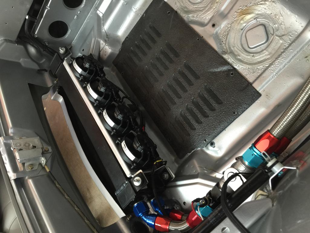
|
   |

 
|
| GregAmy |
May 4 2016, 08:10 PM
Post
#2
|
|
Advanced Member Group: Members Posts: 2,311 Joined: 22-February 13 From: Middletown CT Member No.: 15,565 Region Association: North East States |
QUOTE(Marv's3.6six @ May 4 2016, 10:03 PM)  My question is.... Do I or should go to the trouble of individually fusing each fan circuit? Depends on your expected failure mode and your failure tolerance plan, and what gauge wire you're using for each fan versus the main circuit. If your expected failure mode is a shorted fan or individual wire, and your failure plan requires the other three to continue running, then you should isolate/fuse each individual circuit. If your expected failure mode is the main source wire, and/or you can tolerate 1 or more fans not working (and relying on temp gauges to tell you when that happens), then you can use the main 25A circuit to cover shorts/failures on the individual circuits. Optimally, you'd have a gauge wire appropriate for the main feed (25A fuse covers ~10gauge) and then individual ones for the fan feeds (16 gauge covers 8A). So...how's this stuff gonna fail and what can you tolerate? |
|
|
|
| Catorse |
May 4 2016, 08:19 PM
Post
#3
|
|
Member Group: Members Posts: 194 Joined: 27-August 15 From: Los Angeles Member No.: 19,106 Region Association: Southwest Region |
Why do you feel you even need fans with that setup?
|
|
|
|
| Steve |
May 4 2016, 10:44 PM
Post
#4
|
|
914 Guru Group: Members Posts: 5,614 Joined: 14-June 03 From: Orange County, CA Member No.: 822 Region Association: Southern California |
Even a 3.2 stuck in traffic in the middle of summer with no air flow will need fans
Ask me how I know. A 3.6 has no oil cooler on the motor is even worse. |
|
|
|
| r_towle |
May 4 2016, 11:25 PM
Post
#5
|
|
Custom Member Group: Members Posts: 24,591 Joined: 9-January 03 From: Taxachusetts Member No.: 124 Region Association: North East States |
QUOTE(GregAmy @ May 4 2016, 10:10 PM) QUOTE(Marv's3.6six @ May 4 2016, 10:03 PM) My question is.... Do I or should go to the trouble of individually fusing each fan circuit? Depends on your expected failure mode and your failure tolerance plan, and what gauge wire you're using for each fan versus the main circuit. If your expected failure mode is a shorted fan or individual wire, and your failure plan requires the other three to continue running, then you should isolate/fuse each individual circuit. If your expected failure mode is the main source wire, and/or you can tolerate 1 or more fans not working (and relying on temp gauges to tell you when that happens), then you can use the main 25A circuit to cover shorts/failures on the individual circuits. Optimally, you'd have a gauge wire appropriate for the main feed (25A fuse covers ~10gauge) and then individual ones for the fan feeds (16 gauge covers 8A). So...how's this stuff gonna fail and what can you tolerate? (IMG:style_emoticons/default/agree.gif) What he said. |
|
|
|
| Marv's3.6six |
May 5 2016, 08:47 AM
Post
#6
|
|
Actual member 7" Group: Members Posts: 695 Joined: 22-November 04 From: Huntington Beach, Ca. Member No.: 3,165 Region Association: Southern California |
QUOTE(GregAmy @ May 4 2016, 07:10 PM) QUOTE(Marv's3.6six @ May 4 2016, 10:03 PM) My question is.... Do I or should go to the trouble of individually fusing each fan circuit? Depends on your expected failure mode and your failure tolerance plan, and what gauge wire you're using for each fan versus the main circuit. Yes of course you are right, the car needs the fans in traffic (ask me how I know) and the ideal failure mode is to lose only one fan at a time, so that answers the question. All wiring is 10 gauge. Like I said above I have 4 position fuse block and a partially fabricated harness. I am having difficulty on the bus side of the fuse block as I have not found a method to distribute power (in my head) that I like. The only choice that is simple is to daisy chain 4 push on connectors in series. Additionally I think I want to run a 5th circuit off the bus side to light an idiot light on my multi gauge to indicate the fans are running, that circuit will have a simple inline fuse. Or I can go back to the drawing board and find a 5 position fuse block. |
|
|
|
| GregAmy |
May 5 2016, 09:56 AM
Post
#7
|
|
Advanced Member Group: Members Posts: 2,311 Joined: 22-February 13 From: Middletown CT Member No.: 15,565 Region Association: North East States |
QUOTE(Marv's3.6six @ May 5 2016, 10:47 AM) Yes of course you are right, the car needs the fans in traffic (ask me how I know) and the ideal failure mode is to lose only one fan at a time...All wiring is 10 gauge. Then I recommend a slight adjustment on your design: use smaller gauge wiring and lower-rated fuses for the fan circuits. Or, well, just lower-rated fuses. Reason being, if you hard-ground a fan or its wire, you want that circuit's fuse to pop first before your main one. If the fuses are rated the same, you have no way to ensure that the circuit fuse pops before the main one. Depending on what style of fuse you're using for the main feed, you might look into a "slow blow" version of that fuse. Same rating, but a bit more tolerant to sudden ground (fractions of a second difference.) QUOTE Like I said above I have 4 position fuse block and a partially fabricated harness. I am having difficulty on the bus side of the fuse block as I have not found a method to distribute power (in my head) that I like. You want something like this, a 4-fuse block, one feed in, four feeds out, each circuit fused. Look around in the car audio sources, there are different versions available. http://www.ebay.com/itm/Auto-Car-Boat-10-W...r-/151909113305 (IMG:http://www.914world.com/bbs2/uploads_offsite/i.ebayimg.com-15565-1462464089.1.jpg) |
|
|
|
| ClayPerrine |
May 5 2016, 10:32 AM
Post
#8
|
|
Life's been good to me so far..... Group: Admin Posts: 15,521 Joined: 11-September 03 From: Hurst, TX. Member No.: 1,143 Region Association: NineFourteenerVille |
I would put a fuse between each fan and the relay. That way if one of the fan motors decides to take a (IMG:style_emoticons/default/stromberg.gif) on you, the rest of them keep working.
|
 |
|
| Marv's3.6six |
May 5 2016, 12:07 PM
Post
#9
|
|
Actual member 7" Group: Members Posts: 695 Joined: 22-November 04 From: Huntington Beach, Ca. Member No.: 3,165 Region Association: Southern California |
QUOTE(GregAmy @ May 5 2016, 08:56 AM) QUOTE(Marv's3.6six @ May 5 2016, 10:47 AM) Yes of course you are right, the car needs the fans in traffic (ask me how I know) and the ideal failure mode is to lose only one fan at a time...All wiring is 10 gauge. Then I recommend a slight adjustment on your design: use smaller gauge wiring and lower-rated fuses for the fan circuits. Or, well, just lower-rated fuses. Reason being, if you hard-ground a fan or its wire, you want that circuit's fuse to pop first before your main one. If the fuses are rated the same, you have no way to ensure that the circuit fuse pops before the main one. The plan with individual fusing per fan is to fuse @ 5 amps each, also the indicator lamp I will fuse @ 1 amp with the main fuse @ 25 amps. |
|
|
|
| Marv's3.6six |
May 5 2016, 12:18 PM
Post
#10
|
|
Actual member 7" Group: Members Posts: 695 Joined: 22-November 04 From: Huntington Beach, Ca. Member No.: 3,165 Region Association: Southern California |
This is the 4 position fuse holder I have now. My challenge is to make a custom buss bar feed that looks like a Porsche factory install. This little fuse holder will be fully visible in the front trunk and it has to look right and not just hacked in.
Attached image(s) 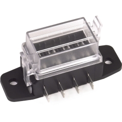
|
|
|
|
| Marv's3.6six |
May 10 2016, 11:38 PM
Post
#11
|
|
Actual member 7" Group: Members Posts: 695 Joined: 22-November 04 From: Huntington Beach, Ca. Member No.: 3,165 Region Association: Southern California |
Here is the first draft of a new 2 relay circuit and individual fuses for operating the 4 fans and idiot light. Automotive DC power guys please comment.
Thanks. Attached thumbnail(s) 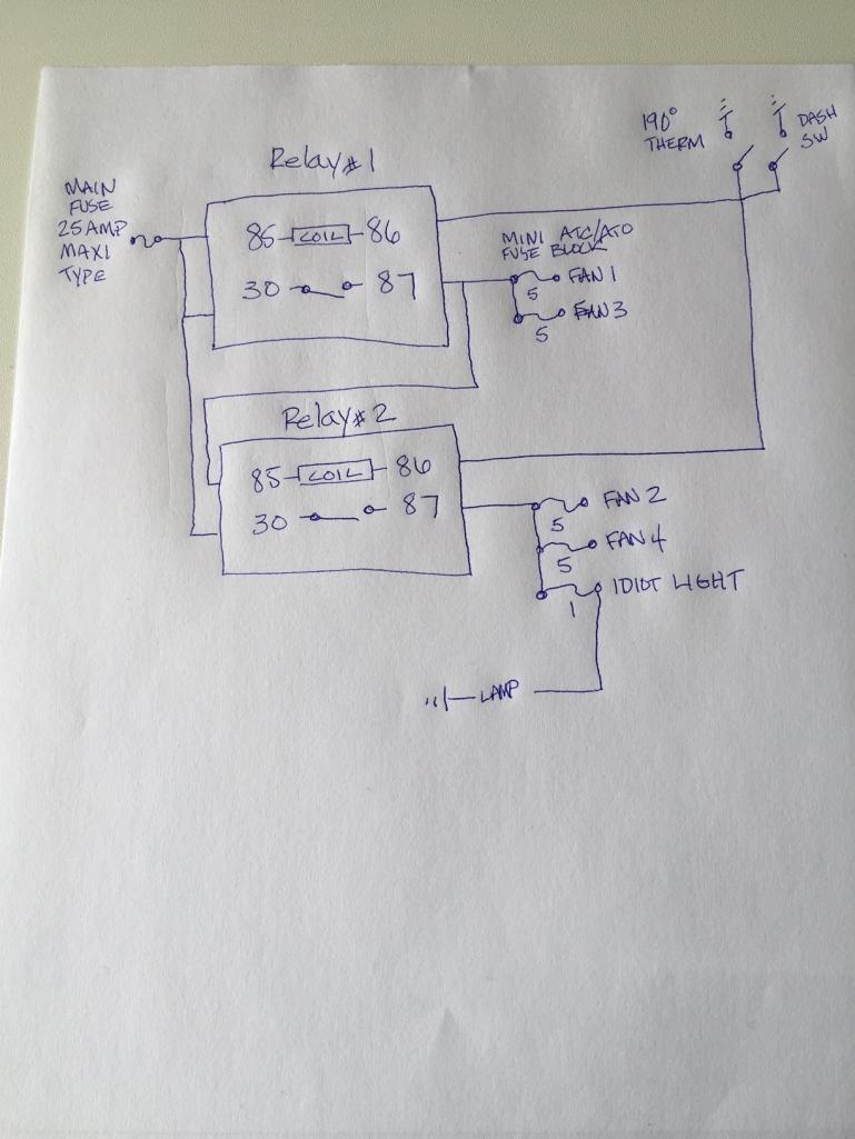
|
|
|
|
| Cairo94507 |
May 11 2016, 07:06 AM
Post
#12
|
|
Michael Group: Members Posts: 9,826 Joined: 1-November 08 From: Auburn, CA Member No.: 9,712 Region Association: Northern California |
|
|
|
|
| GregAmy |
May 11 2016, 07:14 PM
Post
#13
|
|
Advanced Member Group: Members Posts: 2,311 Joined: 22-February 13 From: Middletown CT Member No.: 15,565 Region Association: North East States |
QUOTE(Marv's3.6six @ May 11 2016, 01:38 AM) Here is the first draft of a new 2 relay circuit and individual fuses for operating the 4 fans and idiot light. Automotive DC power guys please comment. Few thoughts. - I don't think you need two relays. Those Bosch relays are good for 30A. - If you do choose to split the circuit, I'd not feed the coil from Relay #2 from the controlled circuit of Relay #1. In that scenario, if you lose Relay #1 then neither will engage and no fans will run. 85s should home separately to main power. - I suggest connecting the 86 terminals of both relay to a common ground terminal, then two separate wires from there, one each to the thermostat and the dash switch. - I don't recommend an idiot light that fires up when the fans are running. That will become distracting as the fans cycle, and you'll eventually tune them out. - If you want notification when you've manually enabled the fans, put an LED in series with the ground side of the dash switch. - If you want notification of when the thermostat switch has closed but you're NOT getting power to the fans, then connect one side of the LED on the 87 circuit of the relay and the other side to the ground side of the thermostat. That should ground the LED through the fans and light it up. That will only alert you for failures in the controlled side of the relay; if the solenoid fails, you'll get no notification (but you have a temp gauge, right? I'm all about KISS. So I'd go with a single relay running all four fans, switches and idiot lights as described above. |
|
|
|
| r_towle |
May 11 2016, 07:28 PM
Post
#14
|
|
Custom Member Group: Members Posts: 24,591 Joined: 9-January 03 From: Taxachusetts Member No.: 124 Region Association: North East States |
I am about KISS to the point that I would have four fuses, four relays and no single point of failure ever.
If I read this right, you have a 25 amp fuse powering all four fans....which seems to be a single point of failure. For me, four identical circuits are are whole lot easier to diagnose. |
|
|
|
| mepstein |
May 11 2016, 07:46 PM
Post
#15
|
|
914-6 GT in waiting Group: Members Posts: 19,316 Joined: 19-September 09 From: Landenberg, PA/Wilmington, DE Member No.: 10,825 Region Association: MidAtlantic Region |
QUOTE(Catorse @ May 4 2016, 10:19 PM) Why do you feel you even need fans with that setup? 3.6 engines have no oil cooler on the engine. So no fan cooled oil cooler unless you build one on the front of the car. |
|
|
|
| wndsnd |
May 11 2016, 08:37 PM
Post
#16
|
|
You wanted a horse, but got a goat. Nobody wants a goat.... Group: Members Posts: 2,861 Joined: 12-February 12 From: North Shore, MA Member No.: 14,124 Region Association: North East States |
QUOTE(Marv's3.6six @ May 5 2016, 02:18 PM) This is the 4 position fuse holder I have now. My challenge is to make a custom buss bar feed that looks like a Porsche factory install. This little fuse holder will be fully visible in the front trunk and it has to look right and not just hacked in. Looks like the one I used for my ignition.. Attached thumbnail(s) 
|
|
|
|
| Marv's3.6six |
May 12 2016, 08:46 AM
Post
#17
|
|
Actual member 7" Group: Members Posts: 695 Joined: 22-November 04 From: Huntington Beach, Ca. Member No.: 3,165 Region Association: Southern California |
GregAmy says: - I don't think you need two relays. Those Bosch relays are good for 30A.
My reasoning for 2 relays is for two reasons, first: I noticed with all 4 fans running on a single relay that there seems to be a significant voltage drop and the fan speed is slightly lower. If I disconnect 2 fans the speed is not so affected by powering 2 fans alone. Additionally the relay “power” conductors (30 & 87) are 12awg. Having the second relay effectively doubles the wire size, also each relay only has to deal with 2 fans. - If you do choose to split the circuit, I'd not feed the coil from Relay #2 from the controlled circuit of Relay #1. In that scenario, if you lose Relay #1 then neither will engage and no fans will run. 85s should home separately to main power. Second reason, I have been using a fast acting 25amp fuse and on occasion it has blown at fan start up! Since I have no headlight motors I am using that circuit from the main under dash fuse panel and the factory harness conductors to the front of the car where the relay is located, those conductors look to be 10 awg. I have measured the draw of each of the fans at 2.48+/- amps per while running. My assumption is that upon startup the current draw must be or exceed 25amps. By wiring the operation of the relays in series I will be decreasing the initial current draw by spreading it out over time? And changing the main fuse type to what is called a Max or Maxi type 25 amp fuse, of which I have no experience with, may help…. lastly re-running home run grounds from each fan to the body ground lug by the headlights, currently they are ganged on a 12 awg wire. I will look into your ideas of LED instead of lamps, thank you. |
|
|
|
|
1 User(s) are reading this topic (1 Guests and 0 Anonymous Users)
0 Members:

|
Lo-Fi Version | Time is now: 10th June 2024 - 05:50 AM |
Invision Power Board
v9.1.4 © 2024 IPS, Inc.