|
|
|
Porsche, and the Porsche crest are registered trademarks of Dr. Ing. h.c. F. Porsche AG.
This site is not affiliated with Porsche in any way. Its only purpose is to provide an online forum for car enthusiasts. All other trademarks are property of their respective owners. |
|
|

  |

| jfort |
 Apr 12 2005, 11:46 AM Apr 12 2005, 11:46 AM
Post
#1
|
|
Senior Member  Group: Members Posts: 1,185 Joined: 5-May 03 From: Findlay, OH Member No.: 652 Region Association: Upper MidWest |
I need some help with the wiring of my new combo gauge from Palo Alto:
The old gauge had a red light for generator, red light for low fuel, oil temp light and oil pressure light green and brake warning light red. The new combo gauge has green, red and blue. What from the old gauge is supposed to go into what on the new gauge? The combo gauges each have 3 connections. ground (ground symbol), positive 12 volts (+ symbol) and the gauge sensor (G), right? Comparing old to new: for example, in the factory manual (914-6) and for my old gauge, the oil temperature sensor, #11, went to the gauge. There was a connection #10 called "terminal #15" that went to both the oil gauge and the fuel gauge (I think). Is that the 12 volts for the gauge? Ground was provided through the casing? For the old oil pressure light, there is a green/red wire on the outside connection and 2 red/white on the inside connection. the red/white wire seems to go to all the bulb connections. Is the green/red the old sensor and the red/white 12 volt power, or what? I didn't label wire #12, fuel sensor well. Is it a green wire do you know? Finally, according to the manual, going across the back of the old gauge from right to left on the horizontal diameter, there was: #9, oil pressure light #8, brake warning light #0, not used #5, generator light but, in fact, according to my notes, #0 was used. there is a black wire on the outside and the red/white on the inside connector. Do you know what this was/is? |
   |

 
|
| scotty914 |
Apr 12 2005, 12:00 PM
Post
#2
|
|
suby torque rules Group: Members Posts: 1,528 Joined: 20-July 03 From: maryland, the land of 25 year Member No.: 924 |
the red with white wire is a key on power wire, it goes to the oil pressure light, tach power, fuel gauge, brake waring light, and oil temp or pressure gauge if you have them.
the turn signal, high beam, and gen light come from other places. these get power from other places |
|
|
|
| lapuwali |
Apr 12 2005, 12:36 PM
Post
#3
|
|
Not another one! Group: Benefactors Posts: 4,526 Joined: 1-March 04 From: San Mateo, CA Member No.: 1,743 |
I don't have a car or a chart handy, but most of these can be worked out. The warning lights usually ground through the switch, so one side is switched +12 (from ignition switch), and the other goes to the engine bay. Look in the engine bay itself for wires of the matching color to know which is which. Same for the fuel level sensor, which can be seen easily if the expansion tank is removed. The oil pressure sensor is on the top of the engine back by the transmission. I can't remember where the oil temp sensor is on the 6. The gauges are similar, in that the G terminal goes to the appropriate sensor. The fuel level sensor has two terminals, one for the light, and the other for the gauge. Same with the oil pressure sender. If you get them hooked up backwards, it's pretty obvious (gauge will peg one way or the other, and the light will stay on all the time), and pretty easy to switch them. The gauges should have three connections each, one for +12, other for the sender, and one for the light. They all ground through the case, with one common ground terminal on the case. The oil temp gauge has only one connection, and you just need to look at the sensor to see what color that is. This is one case where having the correct wiring diagram handy can save you a fair amount of grief. |
|
|
|
| brownaar |
Apr 12 2005, 03:01 PM
Post
#4
|
|
Member Group: Members Posts: 263 Joined: 23-September 04 From: Gate City, VA Member No.: 2,813 Region Association: None |
|
|
|
|
| Dave_Darling |
Apr 13 2005, 01:20 PM
Post
#5
|
|
914 Idiot Group: Members Posts: 15,200 Joined: 9-January 03 From: Silicon Valley / Kailua-Kona Member No.: 121 Region Association: Northern California |
Sounds like you've got a good handle on it. I don't think anything I read was wrong. The black wire on "#0" sounds like the wire that runs the "low-fuel" light. It will be shorted to ground when your fuel level is low enough; the red/white wire provides power, and the light will go on.
--DD |
|
|
|
| jfort |
Apr 15 2005, 01:04 PM
Post
#6
|
|
Senior Member Group: Members Posts: 1,185 Joined: 5-May 03 From: Findlay, OH Member No.: 652 Region Association: Upper MidWest |
going to try the wiring/gauge connection project this w.e.
Attached image(s) 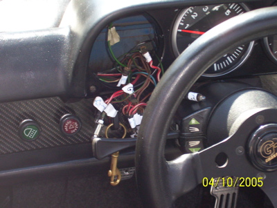
|
|
|
|
| jfort |
Apr 15 2005, 01:05 PM
Post
#7
|
|
Senior Member Group: Members Posts: 1,185 Joined: 5-May 03 From: Findlay, OH Member No.: 652 Region Association: Upper MidWest |
note copy of manual showing gauge connections. if you could only see all my notes and drawings........
Attached image(s) 
|
|
|
|
| jfort |
Apr 15 2005, 01:06 PM
Post
#8
|
|
Senior Member Group: Members Posts: 1,185 Joined: 5-May 03 From: Findlay, OH Member No.: 652 Region Association: Upper MidWest |
gauge back
Attached image(s) 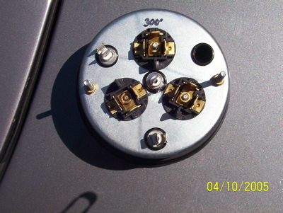
|
|
|
|
| jfort |
Apr 15 2005, 01:08 PM
Post
#9
|
|
Senior Member Group: Members Posts: 1,185 Joined: 5-May 03 From: Findlay, OH Member No.: 652 Region Association: Upper MidWest |
checking the right angle drive for the speedo. will install new one this w.e.
Attached image(s) 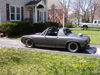
|
|
|
|
| jfort |
Apr 18 2005, 09:53 AM
Post
#10
|
|
Senior Member Group: Members Posts: 1,185 Joined: 5-May 03 From: Findlay, OH Member No.: 652 Region Association: Upper MidWest |
got the old pressure sender off with a crows foot, 17mm I think. wire all the "+" gauge connections together and then attached that to one of the car red/white wires. Did the same thing for the ground connections. This was easier than trying to connect the shorter wires in the car. Then we just hooked each wire from the sender for the gas tank, the oil temp and the oil pressure. Checked continuity just to be sure. I used the former oil pressure idiot light wire as the wire for the pressure gauge. I have not yet run a new wire so that there is both a gauge and a light for oil pressure. All the gauges seem to be working. I have lights for the generator and the low fuel level. Palo Alto did a great job on the gauges. They look great. They aren't much help getting them wired in -- figuring that the car owner can figure it out. But you guys helped me there. THANKS! Finally had a nice weekend to drive, too. I am psyched!!
|
|
|
|
|
1 User(s) are reading this topic (1 Guests and 0 Anonymous Users)
0 Members:

|
Lo-Fi Version | Time is now: 12th July 2025 - 09:24 AM |
Invision Power Board
v9.1.4 © 2025 IPS, Inc.