|
|
|
Porsche, and the Porsche crest are registered trademarks of Dr. Ing. h.c. F. Porsche AG.
This site is not affiliated with Porsche in any way. Its only purpose is to provide an online forum for car enthusiasts. All other trademarks are property of their respective owners. |
|
|

  |

| pilothyer |
 Apr 9 2018, 12:01 PM Apr 9 2018, 12:01 PM
Post
#1
|
|
Member  Group: Members Posts: 838 Joined: 21-May 08 From: N. Alabama Member No.: 9,080 Region Association: South East States |
When using 911 Valve Adjusters, with the early rockers (modified of course) what is the starting point on the adjusters. How much do you screw them in to the rockers before you start the valve train geometry procedure. I would imagine you need to have enough threads in either direction for future valve adjustments, but how much ? Thanks for your support, I am at this critical stage on my engine now .
 |
   |

 
|
| mgphoto |
Apr 9 2018, 12:08 PM
Post
#2
|
|
"If there is a mistake it will find me" Group: Members Posts: 1,339 Joined: 1-April 09 From: Los Angeles, CA Member No.: 10,225 Region Association: Southern California |
Countersinking the hole for the threads will give a bit more adjustment.
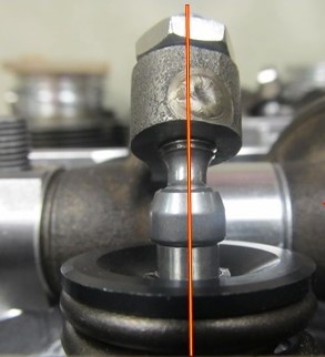
What you want to do is have the rocker aligned straight with the valve at half lift. You may need to install shims under the rocker arm shafts. |
|
|
|
| pilothyer |
Apr 9 2018, 01:19 PM
Post
#3
|
|
Member Group: Members Posts: 838 Joined: 21-May 08 From: N. Alabama Member No.: 9,080 Region Association: South East States |
QUOTE(mgphoto @ Apr 9 2018, 01:08 PM)  Countersinking the hole for the threads will give a bit more adjustment. What you want to do is have the rocker aligned straight with the valve at half lift. You may need to install shims under the rocker arm shafts. Thanks for your input..............I fully understand the objective of setting the correct geometry. My question is this: How much (how many threads) should you leave for future adjustment for greater clearance (backing out the adjuster) I know the adjuster is way long enough for future closing the clearance, but what about for increasing it. Just looking now for a good starting point considering future adjustment both ways. |
|
|
|
| TheCabinetmaker |
Apr 9 2018, 01:47 PM
Post
#4
|
|
I drive my car everyday Group: Members Posts: 8,304 Joined: 8-May 03 From: Tulsa, Ok. Member No.: 666 |
Do you have an adjustable pushrod and dial indicator?
|
|
|
|
| mgphoto |
Apr 9 2018, 01:52 PM
Post
#5
|
|
"If there is a mistake it will find me" Group: Members Posts: 1,339 Joined: 1-April 09 From: Los Angeles, CA Member No.: 10,225 Region Association: Southern California |
QUOTE(pilothyer @ Apr 9 2018, 12:19 PM) QUOTE(mgphoto @ Apr 9 2018, 01:08 PM) Countersinking the hole for the threads will give a bit more adjustment. What you want to do is have the rocker aligned straight with the valve at half lift. You may need to install shims under the rocker arm shafts. Thanks for your input..............I fully understand the objective of setting the correct geometry. My question is this: How much (how many threads) should you leave for future adjustment for greater clearance (backing out the adjuster) I know the adjuster is way long enough for future closing the clearance, but what about for increasing it. Just looking now for a good starting point considering future adjustment both ways. That will be dictated by the amount of material you removed from the rocker and placement of the rocker shaft. When the hole for the adjuster is just and extension of the valve stem, a perfect straight line, looking at it from the side, than it should be positioned correctly. Are you cutting new push rods? |
|
|
|
| pilothyer |
Apr 9 2018, 03:15 PM
Post
#6
|
|
Member Group: Members Posts: 838 Joined: 21-May 08 From: N. Alabama Member No.: 9,080 Region Association: South East States |
QUOTE(The Cabinetmaker @ Apr 9 2018, 02:47 PM) Do you have an adjustable pushrod and dial indicator? Yes I have both and fully understand how to use them. My question is before I start the procedure, how much room should be left for future adjustment if the valve adjuster ever gets too tight (seat wear, valve wear, etc.) |
|
|
|
| pilothyer |
Apr 9 2018, 03:19 PM
Post
#7
|
|
Member Group: Members Posts: 838 Joined: 21-May 08 From: N. Alabama Member No.: 9,080 Region Association: South East States |
QUOTE(mgphoto @ Apr 9 2018, 02:52 PM) QUOTE(pilothyer @ Apr 9 2018, 12:19 PM) QUOTE(mgphoto @ Apr 9 2018, 01:08 PM) Countersinking the hole for the threads will give a bit more adjustment. What you want to do is have the rocker aligned straight with the valve at half lift. You may need to install shims under the rocker arm shafts. Thanks for your input..............I fully understand the objective of setting the correct geometry. My question is this: How much (how many threads) should you leave for future adjustment for greater clearance (backing out the adjuster) I know the adjuster is way long enough for future closing the clearance, but what about for increasing it. Just looking now for a good starting point considering future adjustment both ways. That will be dictated by the amount of material you removed from the rocker and placement of the rocker shaft. When the hole for the adjuster is just and extension of the valve stem, a perfect straight line, looking at it from the side, than it should be positioned correctly. Are you cutting new push rods? Yes, I will be cutting the pushrods after the geometry is correctly set with the adjustable push rod. I am trying to determine how much adjustment should be left at the adjuster for future valve adjustments should the zero gap ever close on me. |
|
|
|
| HAM Inc |
Apr 9 2018, 03:37 PM
Post
#8
|
|
Senior Member Group: Members Posts: 846 Joined: 24-July 06 From: Watkinsville,GA Member No.: 6,499 Region Association: None |
I always shot for it to be about equal thread reveal top and bottom with a smidge more thread for adjusting out cam/lifter wear since that's more likely than a valve tightening, at least with my heads. (IMG:style_emoticons/default/biggrin.gif)
|
|
|
|
| pilothyer |
Apr 9 2018, 03:48 PM
Post
#9
|
|
Member Group: Members Posts: 838 Joined: 21-May 08 From: N. Alabama Member No.: 9,080 Region Association: South East States |
QUOTE(HAM Inc @ Apr 9 2018, 04:37 PM) I always shot for it to be about equal thread reveal top and bottom with a smidge more thread for adjusting out cam/lifter wear since that's more likely than a valve tightening, at least with my heads. (IMG:style_emoticons/default/biggrin.gif) (IMG:style_emoticons/default/pray.gif) Thank you Len, so much. I had begun to think my question was not being understood. I would hate to find out that down the road, I hadn't left enough room for adjustment in that direction and the valve not being able to fully close would be ruined along with those superb heads you did for me. Thanks again to you and to all who supplied input.................Now I can move forward (IMG:style_emoticons/default/biggrin.gif) |
|
|
|
| tejon007 |
Apr 9 2018, 04:43 PM
Post
#10
|
|
Newbie Group: Members Posts: 45 Joined: 10-February 10 From: Northern California Member No.: 11,344 Region Association: None |
Measure the total travel of the adjuster within the safe margins of both full-in and full-out, then turn it in slightly less than half total travel and lock it down. Then measure your push rod length, making sure you set the geometry correctly. Also, remember that you're doing this cold, so the tolerances will tighten up when hot...
Maybe setup the geometry and measure twice, cut once?? (IMG:style_emoticons/default/smile.gif) (IMG:style_emoticons/default/sawzall-smiley.gif) You'll really want to get the correct intake and exhaust gaps set correctly when you're up and running, but if you screwup and it's a little loose...it's far better than burning a valve from being too tight. |
|
|
|
| yeahmag |
Apr 9 2018, 05:21 PM
Post
#11
|
|
Advanced Member Group: Members Posts: 2,424 Joined: 18-April 05 From: Pasadena, CA Member No.: 3,946 Region Association: Southern California |
I've only done it a few times and I always seem to have way more out the "top" than "the bottom". I don't tend to use a lot of shim. Maybe that's a false economy...
Len, how much shim is acceptable? I would think it would take a ton to even it out. |
|
|
|
|
1 User(s) are reading this topic (1 Guests and 0 Anonymous Users)
0 Members:

|
Lo-Fi Version | Time is now: 16th June 2024 - 02:37 AM |
Invision Power Board
v9.1.4 © 2024 IPS, Inc.