|
|
|
Porsche, and the Porsche crest are registered trademarks of Dr. Ing. h.c. F. Porsche AG.
This site is not affiliated with Porsche in any way. Its only purpose is to provide an online forum for car enthusiasts. All other trademarks are property of their respective owners. |
|
|

  |

| second wind |
 Feb 24 2022, 02:05 AM Feb 24 2022, 02:05 AM
Post
#1
|
|
Senior Member  Group: Members Posts: 862 Joined: 30-December 10 From: Los Angeles, California Member No.: 12,543 Region Association: Southern California |
Hello out there....my car has been dying after getting a good warm up but starts the next morning. The tell tale symptom is that the fuel pump does not run when the stall occurs and even after hours of cooling off it still does not start...but it does in the morning....???
So talk on the street is the relay board is too old to work properly.....the description of 914 LTD's improved and rebuilt relay boards matches the symptoms of my car perfectly so as soon as I scrap up the money I will buy one.....meanwhile I have two spare relay boards and one looks really good. Is there a way to bench test the relay board before I swap the boards ?? These cars sure keep you on your toes and a relay board with fresh soldered connections sure sounds appealing so Brad is holding one for me. So back to the swap out....I hate to go to the effort just to install another faulty board. Look forward and appreciate any and all comments and help....thank you very much!!!! gg |
   |

 
|
| 914Sixer |
Feb 24 2022, 07:12 AM
Post
#2
|
|
914 Guru Group: Members Posts: 9,179 Joined: 17-January 05 From: San Angelo Texas Member No.: 3,457 Region Association: Southwest Region |
Yes you can test the board with a multi meter. I have never seen the need to solder the board connections. Quick, simple test is to put meter on resistance test with tone. Put leads at the end of each circuit post and listen for chirp.
|
|
|
|
| Superhawk996 |
Feb 24 2022, 07:46 AM
Post
#3
|
|
914 Guru Group: Members Posts: 7,197 Joined: 25-August 18 From: Woods of N. Idaho Member No.: 22,428 Region Association: Galt's Gulch |
(IMG:style_emoticons/default/agree.gif) with a couple modifications:
There is nothing magical about the relay board. It is actually from the stone age. Just large copper traces inside a plastic housing that runs continuity from point to point. 1) As a former electronics technician it annoys me to no end to see all the forum threads about electrical troubleshooting where the proposed solutions are simply guess work and parts swapping (Note: not targeting @second wind - just a generalization) I've largely stopped trying to participate in those threads because people refuse to use a schematic and a Digital Multi Meter (DMM). I know it might take some time to learn how to read schematics and/or to use a DMM. The reality is that if you're going to play with 50 year old cars, you're going to have to learn sooner or later. Google & YouTube are your friend for learning how to read schematics and to use a DMM. Otherwise: a)You're going to pay $$ to someone skilled enough to use a DMM, a schematic, and then to troubleshoot properly. b)You're going to waste $$ on needless parts and parts swapping c) You're going to pay some other "mechanic" to do the parts swapping and guessing for you which is the worst possible outcome both for time and $$. 2) These boards do have a lot of swagged connections within them as 914 LTD states on the website. However, swagging is a form of crimping that is more reliable than soldering per Auto Industry, Aerospace, and NASA white papers. Yes, it is possible that a swagged connection could be come loose, but it is less likely than one of the soldered connections within the relay board with a cold solder joint, and/or a stress cracked solder joint. Sure you can solder every swagged connector as belt and suspenders, but in reality you're more likely to have a bad solder connection due to a dirty board and/or improper fluxing over the swagged connection than a bad swagged connection itself. If acid core flux is used to do the soldering, you'll have a long term corrosion source on the board itself if the flux is not completely removed. NOTE: I'm not trying to tear down the 914 LTD relay board. I understand why he's offering this as a service as there are bad boards out there with corroded traces, traces screwed up form DAPO's shooting long regulator screw across traces creating shorts, bad potting, and even some with stressed solder joints and/or swagged connections due to corrosion or improper handling over time. I understand why the solder belt and suspenders approach holds appeal and it's not likely to hurt anything. Having de-potted a couple boards myself, his pricing is fair, so is @914sixers for restored boards. It takes a lot of labor to remove the potting, continuity check, redo these boards with new potting If you really want to do the whole bench test routine, do as @914sixer suggests and simply test all connections for continuity at room temperature. If you want to go the next level and really think heat cycling is your problem, warm the board in your oven to about 150F - 200F then test continuity again. If you have the board de-potted, you could also use a heat gun (carefully) at the specific swagged connections of interest. Going back to point #1, you don't have to test all continuity across the whole board, just those traces that handle the fuel pump, the ignition coil, the tachometer (which is also connected to the coil), and the ECU feeds (if fuel injected), In OP you don't mention if you've already ruled out the relay itself, and whether you've verified the integrity and power feeds to the components (coil, pump, ECU) itself both hot and cold. I'd do that before jumping to swapping relay boards. |
|
|
|
| second wind |
Feb 24 2022, 11:42 AM
Post
#4
|
|
Senior Member Group: Members Posts: 862 Joined: 30-December 10 From: Los Angeles, California Member No.: 12,543 Region Association: Southern California |
QUOTE(Superhawk996 @ Feb 24 2022, 05:46 AM)  (IMG:style_emoticons/default/agree.gif) with a couple modifications: There is nothing magical about the relay board. It is actually from the stone age. Just large copper traces inside a plastic housing that runs continuity from point to point. 1) As a former electronics technician it annoys me to no end to see all the forum threads about electrical troubleshooting where the proposed solutions are simply guess work and parts swapping (Note: not targeting @second wind - just a generalization) I've largely stopped trying to participate in those threads because people refuse to use a schematic and a Digital Multi Meter (DMM). I know it might take some time to learn how to read schematics and/or to use a DMM. The reality is that if you're going to play with 50 year old cars, you're going to have to learn sooner or later. Google & YouTube are your friend for learning how to read schematics and to use a DMM. Otherwise: a)You're going to pay $$ to someone skilled enough to use a DMM, a schematic, and then to troubleshoot properly. b)You're going to waste $$ on needless parts and parts swapping c) You're going to pay some other "mechanic" to do the parts swapping and guessing for you which is the worst possible outcome both for time and $$. 2) These boards do have a lot of swagged connections within them as 914 LTD states on the website. However, swagging is a form of crimping that is more reliable than soldering per Auto Industry, Aerospace, and NASA white papers. Yes, it is possible that a swagged connection could be come loose, but it is less likely than one of the soldered connections within the relay board with a cold solder joint, and/or a stress cracked solder joint. Sure you can solder every swagged connector as belt and suspenders, but in reality you're more likely to have a bad solder connection due to a dirty board and/or improper fluxing over the swagged connection than a bad swagged connection itself. If acid core flux is used to do the soldering, you'll have a long term corrosion source on the board itself if the flux is not completely removed. NOTE: I'm not trying to tear down the 914 LTD relay board. I understand why he's offering this as a service as there are bad boards out there with corroded traces, traces screwed up form DAPO's shooting long regulator screw across traces creating shorts, bad potting, and even some with stressed solder joints and/or swagged connections due to corrosion or improper handling over time. I understand why the solder belt and suspenders approach holds appeal and it's not likely to hurt anything. Having de-potted a couple boards myself, his pricing is fair, so is @914sixers for restored boards. It takes a lot of labor to remove the potting, continuity check, redo these boards with new potting If you really want to do the whole bench test routine, do as @914sixer suggests and simply test all connections for continuity at room temperature. If you want to go the next level and really think heat cycling is your problem, warm the board in your oven to about 150F - 200F then test continuity again. If you have the board de-potted, you could also use a heat gun (carefully) at the specific swagged connections of interest. Going back to point #1, you don't have to test all continuity across the whole board, just those traces that handle the fuel pump, the ignition coil, the tachometer (which is also connected to the coil), and the ECU feeds (if fuel injected), In OP you don't mention if you've already ruled out the relay itself, and whether you've verified the integrity and power feeds to the components (coil, pump, ECU) itself both hot and cold. I'd do that before jumping to swapping relay boards. Thank you Superhawk....I did some relay swapping and ended up putting all new 914 Rubber relays on the board. Not hearing the fuel pump go on when turning the key makes me want to rule out a bad fuel pump since it works fine when cold and the new relays make me think that is not the problem either. I would love to hear more about these 50 year old relay boards.....do they really go bad or not? And when they do go bad what is the usual culprit? Thank you all very much! gg |
|
|
|
| Superhawk996 |
Feb 24 2022, 12:19 PM
Post
#5
|
|
914 Guru Group: Members Posts: 7,197 Joined: 25-August 18 From: Woods of N. Idaho Member No.: 22,428 Region Association: Galt's Gulch |
QUOTE(second wind @ Feb 24 2022, 12:42 PM) Thank you Superhawk....I did some relay swapping and ended up putting all new 914 Rubber relays on the board. Not hearing the fuel pump go on when turning the key makes me want to rule out a bad fuel pump since it works fine when cold and the new relays make me think that is not the problem either. I would love to hear more about these 50 year old relay boards.....do they really go bad or not? And when they do go bad what is the usual culprit? Thank you all very much! gg There's a lot of assumption built into what you just laid out. Just sayin'. Methodical troubleshooting with a schematic and DMM to root cause for the problem at hand is the fastest way to solve the problem. There really isn't anything complicated in the relay board I'll try to post a picture later. Simply very thick, copper trace interconnects that go point to point. Various relay socket posts and spade connections secured in there with mostly swagged connections and 10 soldered connections, 6 of which serve the voltage regulator circuit. All the relay connections are swagged along with the main harness in/out pins. The other 4 soldered connection go the the spade connectors labeled as roman numerals I-IV in the graphic (below) Here's a very good internal view of the traces and the circuit connections posted by SirAndy about 14 years ago. 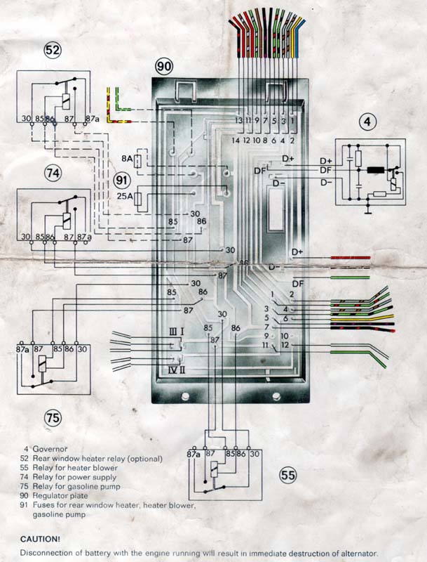 |
|
|
|
| lesorubcheek |
Feb 24 2022, 12:45 PM
Post
#6
|
|
Member Group: Members Posts: 193 Joined: 21-April 21 From: Florida Member No.: 25,463 Region Association: South East States |
Tracking down intermittent electrical problems ain't fun. When we were working on mcm minesweepers, the rule was to suspect cables first, components second. Really it pertains to any junction where an electrical connection relies on physical contact, and those swaged pins in the circuit board fit this scenario. Not saying that's for sure where your problem lies, but it's a possibility. Another rule says to try and pick low hanging fruit first, so easy things that are external don't hurt to eliminate before digging into a complex can of worms.
There's a great reference on Mr. Bowlby's site (absolutely incredible person sharing a wealth of knowledge) dealing with fuel pump troubleshooting. Here's the link. https://bowlsby.net/914/Classic/TechNotebook.htm There's "Fuel Pump Circuit Troubleshooting Flow Charts" and "Fuel Pump Circuit Troubleshooting D-Jet only". Each is a pdf. Maybe these can give some suggestions as to a path for finding where the problem lies. Dan |
|
|
|
| Superhawk996 |
Feb 24 2022, 03:31 PM
Post
#7
|
|
914 Guru Group: Members Posts: 7,197 Joined: 25-August 18 From: Woods of N. Idaho Member No.: 22,428 Region Association: Galt's Gulch |
Here you go un-potted board. This is posted as mirror image of SirAndys that is looking from top of board down “thru” the board. This is the physical view from under the board looking up.
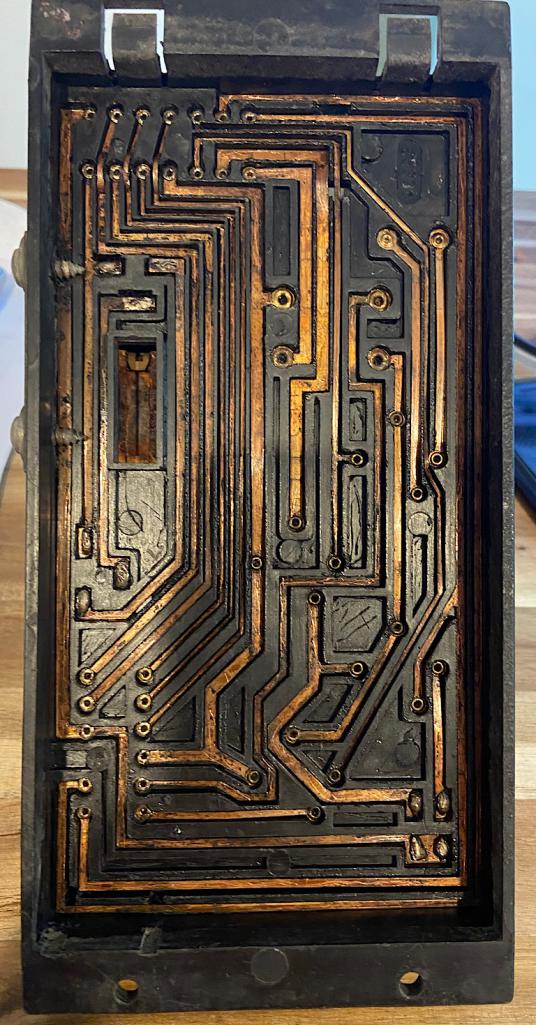 Note DAPO screws that are too long crossing trace connecting it to the voltage regulator housing (IMG:style_emoticons/default/headbang.gif) |
|
|
|
| Puebloswatcop |
Feb 24 2022, 04:00 PM
Post
#8
|
|
Senior Member Group: Members Posts: 1,555 Joined: 27-December 14 From: Mineola, Texas Member No.: 18,258 Region Association: Southwest Region |
(IMG:style_emoticons/default/agree.gif) All of the above. Using a dDMM is not rocket science and they really arent that expensive. On these cars a definatly needed tool. Iread all the hype about soldering all of these connections. After stripping the bottom of my board and checking and rechecking the points, from both the top and the bottom found all of the swaged joints to be fine.
Just take your time and check each cirquit one at a time. The problem is most likely not the board. Probably a bad relay or some other problem in the electrical system. |
|
|
|
| Bartlett 914 |
Feb 24 2022, 04:53 PM
Post
#9
|
|
Advanced Member Group: Members Posts: 2,218 Joined: 30-August 05 From: South Elgin IL Member No.: 4,707 Region Association: Upper MidWest |
A relay board has no electronics. It is a buss bar to relay and connector pins distributor. If it is intermittent than one or more of these connections is failing. The staking is very good and normally shouldn't fail but if the board is intermittent then the connection IS failing. Locating the connection and soldering it is the best solution. One problem using a DMM is the fact that the meter uses very small current. It can measure zero ohms and the connection can still be bad under load. What is needed is a higher current setup for "Ringing out" the connections. If your card is measured with a DMM as ok but you know there is a problem remaining in the board then one way to ring out the board is by using a voltage source and a light bulb. A light bulb using some power would be best. Maybe a headlight could be used. You need something with at least a couple of amps for testing.
|
|
|
|
| johnhora |
Feb 24 2022, 05:08 PM
Post
#10
|
|
Senior Member Group: Members Posts: 888 Joined: 7-January 03 From: Derby City KY Member No.: 107 Region Association: None |
Check the wire harness at the fuel pump....
I have repaired a few in the past where the wires are in bad shape and make for intermittent connections. Sometimes I had to go back on the harness and splice in a new wire to eliminate the bad wires. Leaky fuel lines and pumps corrode the wires and connector. |
|
|
|
| JeffBowlsby |
Feb 24 2022, 06:34 PM
Post
#11
|
|
914 Wiring Harnesses & Beekeeper Group: Members Posts: 8,963 Joined: 7-January 03 From: San Ramon CA Member No.: 104 Region Association: None |
The word is 'swaged', not swagged.
But I dont think they are swaged, just riveted. |
|
|
|
| 930cabman |
Feb 24 2022, 06:46 PM
Post
#12
|
|
Advanced Member Group: Members Posts: 4,166 Joined: 12-November 20 From: Buffalo Member No.: 24,877 Region Association: North East States |
I assume the riveted/buss bar connection fails from time to time. Either this connection, the female sockets or a break in the copper buss bar can be the only potential failure
Basically it is from the stone age, good one Phil |
|
|
|
| Superhawk996 |
Feb 24 2022, 08:43 PM
Post
#13
|
|
914 Guru Group: Members Posts: 7,197 Joined: 25-August 18 From: Woods of N. Idaho Member No.: 22,428 Region Association: Galt's Gulch |
QUOTE(JeffBowlsby @ Feb 24 2022, 07:34 PM) The word is 'swaged', not swagged. But I dont think they are swaged, just riveted. Indeed you are correct. (IMG:style_emoticons/default/beerchug.gif) The swage is the tooling used to cold form the metal into what becomes the “rivet” head we can see. Either way, the result is a sound mechanical deformation that drives the post outward within the hole and compresses downward onto the copper trace. |
|
|
|
| raynekat |
Feb 24 2022, 09:10 PM
Post
#14
|
|
Advanced Member Group: Members Posts: 2,169 Joined: 30-December 14 From: Coeur d'Alene, Idaho Member No.: 18,263 Region Association: Pacific Northwest |
QUOTE(Superhawk996 @ Feb 24 2022, 05:46 AM) (IMG:style_emoticons/default/agree.gif) with a couple modifications: There is nothing magical about the relay board. It is actually from the stone age. Just large copper traces inside a plastic housing that runs continuity from point to point. This is so true. Get a multimeter and a wiring schematic for the relay board and have at it. On my 914-6 relay board, I found two (2) of the copper traces that had a break in them that needed a bit of solder and all was good. If you are seeing sporadic stuff happening during the day, there's a good chance that a trace has a small break in it that shows itself from time to time. Definitely not rocket science testing this relay board with a multimeter. |
|
|
|
| volksaddict |
Feb 24 2022, 09:12 PM
Post
#15
|
|
Newbie Group: Members Posts: 32 Joined: 29-January 11 From: southwest Member No.: 12,645 Region Association: Southwest Region |
I appreciate this info! I have. a fuel pump power issue to resolve soon.
|
|
|
|
| second wind |
Feb 24 2022, 11:54 PM
Post
#16
|
|
Senior Member Group: Members Posts: 862 Joined: 30-December 10 From: Los Angeles, California Member No.: 12,543 Region Association: Southern California |
I am so appreciative you guys!!!!!!!!!!!!!! I will end up cleaning up my best looking spare and installing it but going down the Bowsley procedure sure makes sense...I will prevail !!!!
gg |
|
|
|
| second wind |
Feb 26 2022, 12:54 AM
Post
#17
|
|
Senior Member Group: Members Posts: 862 Joined: 30-December 10 From: Los Angeles, California Member No.: 12,543 Region Association: Southern California |
QUOTE(second wind @ Feb 24 2022, 09:54 PM) I am so appreciative you guys!!!!!!!!!!!!!! I will end up cleaning up my best looking spare and installing it but going down the Bowsley procedure sure makes sense...I will prevail !!!! gg Just to make sure I cover all bases....rumor has it that the ECU never fails....am I maybe overlooking a source of my issue? Thank you, gg |
|
|
|
| dirk2056 |
Feb 26 2022, 07:22 AM
Post
#18
|
|
Member Group: Members Posts: 95 Joined: 31-July 17 From: cincinnati/Eastside Member No.: 21,304 Region Association: Middle East |
(IMG:style_emoticons/default/agree.gif) almost 100% of the electrical problems I found on my car were ground issues burnt brown wire or poor connections good luck!!!
|
|
|
|
| Superhawk996 |
Feb 26 2022, 08:33 AM
Post
#19
|
|
914 Guru Group: Members Posts: 7,197 Joined: 25-August 18 From: Woods of N. Idaho Member No.: 22,428 Region Association: Galt's Gulch |
QUOTE(second wind @ Feb 26 2022, 01:54 AM) QUOTE(second wind @ Feb 24 2022, 09:54 PM) I am so appreciative you guys!!!!!!!!!!!!!! I will end up cleaning up my best looking spare and installing it but going down the Bowsley procedure sure makes sense...I will prevail !!!! gg Just to make sure I cover all bases....rumor has it that the ECU never fails....am I maybe overlooking a source of my issue? Thank you, gg In my best Captain Krusty imitation, offered in the spirit of friendship and a desire to help you solve your problem and get driving your car. Stop guessing at what it might be. Get a DMM, get a schematic and let's start methodically troubleshooting it and stop the guessing. (IMG:style_emoticons/default/happy11.gif) @second wind |
|
|
|
| iankarr |
Feb 26 2022, 09:14 AM
Post
#20
|
|
The wrencher formerly known as Cuddy_K Group: Members Posts: 2,561 Joined: 22-May 15 From: Heber City, UT Member No.: 18,749 Region Association: Intermountain Region |
(IMG:style_emoticons/default/agree.gif)
It’s important to collect hard data on these issues. Otherwise you may think you’ve solved the problem, only to have it crop up again. For example…you replace the relay board and everything works fine. Then, a month later it starts happening again. You finally start to methodically test and realize there was a loose connection in the harness plug and the act of replacing it on a new board improved the contact enough to think the board was the issue. BTDT. Like Ringo….I say this with peace and love, but if you want to solve problems with the least amount of frustration, expense, and rides on a flatbed, implement a testing procedure that definitively identifies the problem. If, at the end of the process you can’t say with specificity exactly what the issue was, you’re only guessing that the problem was solved. If it were me… -Use known good relays. All of them. Don’t always assume that new=good. -Confirm that there’s power at the pump leads -Have a friend repeatedly turn the key to the ACC position while you grip the relay board in various positions. If you hear the pump cycle while pressing relays or the bottom of the board, you’ve found the issue. (This is actually what happened on my BB). Bottom line…gremlins are crafty. Being able able to re-create the problem at will…or identify the break in continuity on a DMM is the only way you can be sure you’ve slayed this beast! |
|
|
|
|
1 User(s) are reading this topic (1 Guests and 0 Anonymous Users)
0 Members:

|
Lo-Fi Version | Time is now: 1st July 2025 - 12:51 AM |
Invision Power Board
v9.1.4 © 2025 IPS, Inc.