|
|
|
Porsche, and the Porsche crest are registered trademarks of Dr. Ing. h.c. F. Porsche AG.
This site is not affiliated with Porsche in any way. Its only purpose is to provide an online forum for car enthusiasts. All other trademarks are property of their respective owners. |
|
|

  |

| jim_hoyland |
 Aug 14 2024, 04:29 PM Aug 14 2024, 04:29 PM
Post
#1
|
|
Get that VIN ?  Group: Members Posts: 10,092 Joined: 1-May 03 From: Sunset Beach, CA Member No.: 643 Region Association: Southern California |
I want to bench test a 4 spade ( original style ) headlight relay. What can I do? Have a 12v source,ohmeter,and aligator clips.
I'd like to test and listen for that "click" |
   |

 
|
| Superhawk996 |
Aug 14 2024, 04:54 PM
Post
#2
|
|
914 Guru Group: Members Posts: 7,921 Joined: 25-August 18 From: Woods of N. Idaho Member No.: 22,428 Region Association: Galt's Gulch |
 Terminal 56 is 12v Terminal “S” is ground and normally runs through the column switch as your control signal. That will make it click With no power connected to the relay - you should have continuity from terminal 56 to 56a. There should be no continuity between terminal 56 and terminal “F”. If you want to test it as in car. 12v to terminal 56 but don’t connect the “S” terminal to ground . . . Yet Should have 12v on terminal 56a. 0v on terminal “F” Now connect terminal “S” to ground - relay clicks Should have 12v on terminal “F”, 0v on terminal 56a [EDIT] forgot to mention this is a latching relay so each click of the solenoid will reverse the state of pins F and 56a. So, if you start this test and get opposite 0v and 12v readings from what I have written, click the relay and the state should reverse. |
|
|
|
| anderssj |
Aug 14 2024, 06:54 PM
Post
#3
|
|
Dog is my copilot... Group: Members Posts: 1,793 Joined: 28-January 03 From: VA Member No.: 207 Region Association: MidAtlantic Region |
This might help:
http://www.914world.com/bbs2/index.php?sho...77&hl=Latch (IMG:style_emoticons/default/idea.gif) |
|
|
|
| Superhawk996 |
Aug 14 2024, 08:06 PM
Post
#4
|
|
914 Guru Group: Members Posts: 7,921 Joined: 25-August 18 From: Woods of N. Idaho Member No.: 22,428 Region Association: Galt's Gulch |
QUOTE(anderssj @ Aug 14 2024, 08:54 PM)  This might help: http://www.914world.com/bbs2/index.php?sho...77&hl=Latch (IMG:style_emoticons/default/idea.gif) (IMG:style_emoticons/default/aktion035.gif) I forgot you wrote that up. Nice job! Bookmarked. |
|
|
|
| jim_hoyland |
Aug 17 2024, 11:58 AM
Post
#5
|
|
Get that VIN ? Group: Members Posts: 10,092 Joined: 1-May 03 From: Sunset Beach, CA Member No.: 643 Region Association: Southern California |
Ran your tests on another relay that has 5 spades.
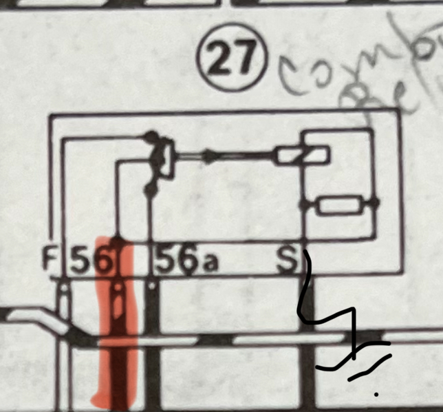
The instructions show a pin “30” that connects to 56 How does 30 and 56 work ?; and what if 30 is left unconnected in the car ? Attached thumbnail(s) 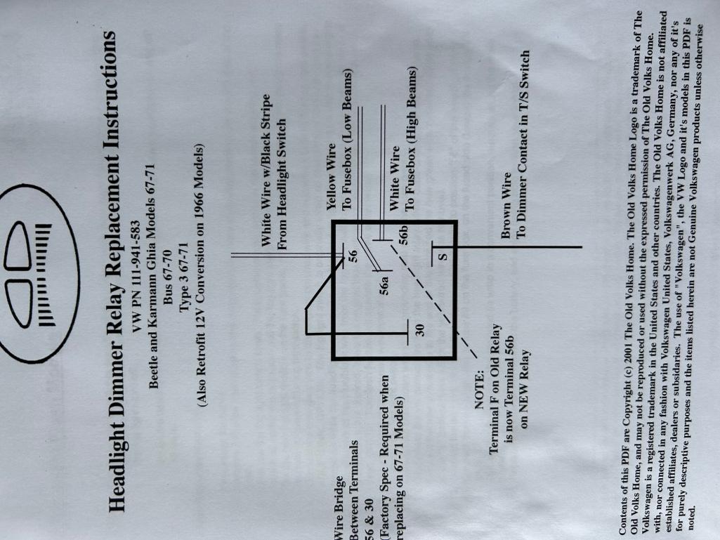
|
|
|
|
| Superhawk996 |
Aug 17 2024, 12:12 PM
Post
#6
|
|
914 Guru Group: Members Posts: 7,921 Joined: 25-August 18 From: Woods of N. Idaho Member No.: 22,428 Region Association: Galt's Gulch |
On 5 pin relay that superseded the OEM 4 pin relay, Pin 30 cannot be left disconnected.
Pin 30 is the solenoid - needs to be connected to 12v which is coming in on pin 56. 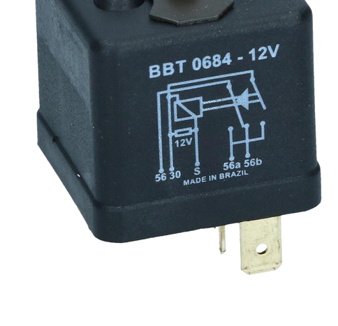 |
|
|
|
| jim_hoyland |
Aug 17 2024, 12:15 PM
Post
#7
|
|
Get that VIN ? Group: Members Posts: 10,092 Joined: 1-May 03 From: Sunset Beach, CA Member No.: 643 Region Association: Southern California |
QUOTE(Superhawk996 @ Aug 17 2024, 11:12 AM) On 5 pin relay that superseded the OEM 4 pin relay, Pin 30 cannot be left disconnected. Pin 30 is the solenoid - needs to be connected to 12v which is coming in on pin 56. K |
|
|
|
|
1 User(s) are reading this topic (1 Guests and 0 Anonymous Users)
0 Members:

|
Lo-Fi Version | Time is now: 29th June 2026 - 09:59 AM |
Invision Power Board
v9.1.4 © 2026 IPS, Inc.