|
|
|
Porsche, and the Porsche crest are registered trademarks of Dr. Ing. h.c. F. Porsche AG.
This site is not affiliated with Porsche in any way. Its only purpose is to provide an online forum for car enthusiasts. All other trademarks are property of their respective owners. |
|
|

  |

| Ron914 |
 Apr 28 2025, 10:52 PM Apr 28 2025, 10:52 PM
Post
#1
|
|
Member  Group: Members Posts: 468 Joined: 19-April 22 From: Huntington Beach,Ca Member No.: 26,487 Region Association: Southern California |
I needed to rebuild my MPS but Chris Foley is out of the kits due to no longer having a supplier of the BE-CU diaphragms . I was lucky enough to have a member here offer to sell me his spare parts kit from Chris (Thanks Tom). His kit did not have the instructions with it so I am wondering if anyone has a copy of those instructions?
|
   |

 
|
| MDTerp |
Apr 29 2025, 04:26 AM
Post
#2
|
|
Member Group: Members Posts: 115 Joined: 20-May 08 From: Maryland Member No.: 9,075 Region Association: MidAtlantic Region |
|
|
|
|

| Ron914 |
Apr 29 2025, 08:27 AM
Post
#3
|
|
Member Group: Members Posts: 468 Joined: 19-April 22 From: Huntington Beach,Ca Member No.: 26,487 Region Association: Southern California |
QUOTE(MDTerp @ Apr 29 2025, 05:26 AM)  Thank you Michael. @MDTerp I will have to look these over carefully so I don't make any mistakes . I do have a couple of questions . It says to use either a M12X1.0 or a M14X10 tap to clean up the threads from the epoxy/sealant , Why two different sizes of taps ? I see your caliper measurements are more precise than my old analog one , should I purchase a new digital caliper for precise measurements (is it that critical ?) For the tools I have with the kit pictured here . This just looks like a standard screwdriver (nothing special ) and the other is the hex tool , is this only a tool or is it also installed as a replacement part ? I think that's it for now until I get a new caliper and taps then drill out my rivets and get replacement screws ( why are two different sizes of screws mentioned ,1-6-32 or 8-32 ,which is better ? 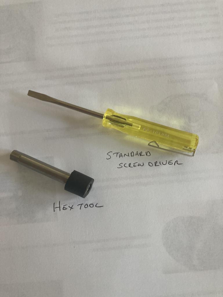 |
|
|
|
| rjames |
Apr 29 2025, 08:50 AM
Post
#4
|
|
I'm made of metal Group: Members Posts: 4,414 Joined: 24-July 05 From: Shoreline, WA Member No.: 4,467 Region Association: Pacific Northwest |
The hex tool is used in conjunction with the screwdriver.
I recommend you go to Anders web site to learn how the MPS works. MPS Info In brief, there are 3 main adjustment mechanisms: the inner screw (adjust with screw driver), the outer screw (adjust with hex tool) and full load stop screw (adjust with Allen wrench if using the new one that came with the kit, or screw driver if using the original). The inner screw will also turn the outer screw unless you keep the outer screw from turning by using the hex tool while adjusting the inner screw (the screw driver fits inside the hex tool). Either tap size will work. Just depends on how bad your threads are after removing the original full load drop screw. Go slow when trying to remove the screw. Trying to force it to turn before moving all the resin/glue will result in having to drill it out. The other tool you’ll likely need is a wide band O2 sensor to tune the MPS after you rebuild it. Good luck! |
|
|
|
| ChrisFoley |
Apr 29 2025, 08:54 AM
Post
#5
|
|
I am Tangerine Racing Group: Members Posts: 8,016 Joined: 29-January 03 From: Bolton, CT Member No.: 209 Region Association: None |
The reason I recommend using those smaller taps as scrapers instead of chasing with the correct tap - no need to buy an expensive tool to use once when something already in the toolbox will work.
|
|
|
|
| ChrisFoley |
Apr 29 2025, 08:57 AM
Post
#6
|
|
I am Tangerine Racing Group: Members Posts: 8,016 Joined: 29-January 03 From: Bolton, CT Member No.: 209 Region Association: None |
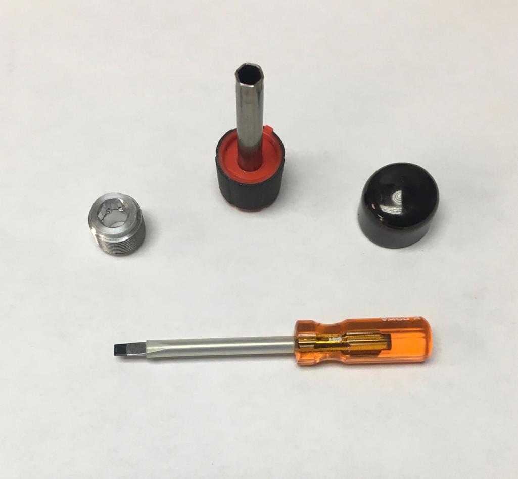
That's an old tool set pictured. Currently, I shorten the handle of the flat screwdriver so it will fit in the engine compartment better, and I sleeve the shank with hard plastic tubing to help keep it centered in the hex tool. The hex tool now has a nice knob on the end instead of a glued on piece of rubber tubing.
 |
|
|
|
| ChrisFoley |
Apr 29 2025, 09:05 AM
Post
#7
|
|
I am Tangerine Racing Group: Members Posts: 8,016 Joined: 29-January 03 From: Bolton, CT Member No.: 209 Region Association: None |
Hi Ron,
I was just on the phone with Tom yesterday. (IMG:style_emoticons/default/smile.gif) |
|
|
|
| Ron914 |
Apr 29 2025, 09:31 AM
Post
#8
|
|
Member Group: Members Posts: 468 Joined: 19-April 22 From: Huntington Beach,Ca Member No.: 26,487 Region Association: Southern California |
QUOTE(rjames @ Apr 29 2025, 09:50 AM) The hex tool is used in conjunction with the screwdriver. I recommend you go to Anders web site to learn how the MPS works. MPS Info In brief, there are 3 main adjustment mechanisms: the inner screw (adjust with screw driver), the outer screw (adjust with hex tool) and full load stop screw (adjust with Allen wrench if using the new one that came with the kit, or screw driver if using the original). The inner screw will also turn the outer screw unless you keep the outer screw from turning by using the hex tool while adjusting the inner screw (the screw driver fits inside the hex tool). Either tap size will work. Just depends on how bad your threads are after removing the original full load drop screw. Go slow when trying to remove the screw. Trying to force it to turn before moving all the resin/glue will result in having to drill it out. The other tool you’ll likely need is a wide band O2 sensor to tune the MPS after you rebuild it. Good luck! @rjames Thanks for the information.I am a newbie when it comes to learning the workings of my 914 ,it has been quite a learning experience for me and a lot of fun .After 3+ years now I am almost there.I did purchase a AEM gauge pictured below for tuning my MPS for a 2056 motor . So it sounds like I don't need to order 2 taps , I think I will just order the M12X1.0 . How about the replacement screws for the drilled out rivets ?What size would be best 6/32 or 8/32 ?  |
|
|
|
| Ron914 |
Apr 29 2025, 09:34 AM
Post
#9
|
|
Member Group: Members Posts: 468 Joined: 19-April 22 From: Huntington Beach,Ca Member No.: 26,487 Region Association: Southern California |
QUOTE(ChrisFoley @ Apr 29 2025, 10:05 AM) Tom is a great guy and now a friend . (IMG:style_emoticons/default/cheer.gif) |
|
|
|
| emerygt350 |
Apr 29 2025, 09:49 AM
Post
#10
|
|
Advanced Member Group: Members Posts: 3,423 Joined: 20-July 21 From: Upstate, NY Member No.: 25,740 Region Association: North East States |
Those look like good improvements on an already great tool.
Ron, after you get the mps rebuilt and initial settings done, you are probably going to want to look at the induction curve. I am happy to send you mine but considering it is only 33 dollars on Amazon, it probably wouldn't make sense. https://a.co/d/bGI6bUO The curve is critical for the mps (you can see it on pbanders site). If you have that right on the bench I have found tuning the MPS in the car is much easier. Really just a matter of richenining or leaning with the inner screw and setting the full load stop to taste at WOT. |
|
|
|
| rjames |
Apr 29 2025, 10:10 AM
Post
#11
|
|
I'm made of metal Group: Members Posts: 4,414 Joined: 24-July 05 From: Shoreline, WA Member No.: 4,467 Region Association: Pacific Northwest |
QUOTE How about the replacement screws for the drilled out rivets ?What size would be best 6/32 or 8/32 ? Don't overthink it. If both sizes are in the documentation, then it's safe to say either will work. IIRC, after drilling them out I just went to home depot and just found something that fit. |
|
|
|
| ChrisFoley |
Apr 29 2025, 10:37 AM
Post
#12
|
|
I am Tangerine Racing Group: Members Posts: 8,016 Joined: 29-January 03 From: Bolton, CT Member No.: 209 Region Association: None |
I've been including M4 screws & nuts for a few years.
|
|
|
|
| MDTerp |
Apr 29 2025, 01:05 PM
Post
#13
|
|
Member Group: Members Posts: 115 Joined: 20-May 08 From: Maryland Member No.: 9,075 Region Association: MidAtlantic Region |
For me it was also very helpful to install a vacuum gauge off of a T from the MPS hose. This helped know when at full load and part load while watching the AFR. It helped to see what vacuum the MPS was seeing and how it responded.
|
|
|
|
| emerygt350 |
Apr 29 2025, 03:20 PM
Post
#14
|
|
Advanced Member Group: Members Posts: 3,423 Joined: 20-July 21 From: Upstate, NY Member No.: 25,740 Region Association: North East States |
QUOTE(MDTerp @ Apr 29 2025, 01:05 PM) For me it was also very helpful to install a vacuum gauge off of a T from the MPS hose. This helped know when at full load and part load while watching the AFR. It helped to see what vacuum the MPS was seeing and how it responded. Exactly, Ron bought a vacuum gauge as well as the afr. I run mine off the decel valve hose from the plenum. |
|
|
|
| TargaToy |
Apr 29 2025, 07:09 PM
Post
#15
|
|
-NONSOLIS RADIOS SEDIOUIS FULMINA MITTO- Group: Members Posts: 714 Joined: 26-March 10 From: DelMarVa Peninsula Member No.: 11,509 Region Association: MidAtlantic Region |
Well crap. I didn’t realize there was no longer a supply of the diaphragms. Does this mean it’s not worth sprucing up and retaining a D-Jet system if this vital component will eventually be completely unavailable/unrepairable?
|
|
|
|
| emerygt350 |
Apr 29 2025, 07:29 PM
Post
#16
|
|
Advanced Member Group: Members Posts: 3,423 Joined: 20-July 21 From: Upstate, NY Member No.: 25,740 Region Association: North East States |
I believe Chris is looking for a replacement.
|
|
|
|
| Ron914 |
Apr 29 2025, 07:47 PM
Post
#17
|
|
Member Group: Members Posts: 468 Joined: 19-April 22 From: Huntington Beach,Ca Member No.: 26,487 Region Association: Southern California |
QUOTE(TargaToy @ Apr 29 2025, 08:09 PM) Well crap. I didn’t realize there was no longer a supply of the diagrams. Does this mean it’s not worth sprucing up and retaining a D-Jet system if this vital component will eventually be completely unavailable/unrepairable? I spoke to Chris last week and he is close to finding a manufacturer for the new diaphragms and a new material better that the old BE-CU and hopes to have them by the end of the year. |
|
|
|
| Ron914 |
Apr 29 2025, 08:48 PM
Post
#18
|
|
Member Group: Members Posts: 468 Joined: 19-April 22 From: Huntington Beach,Ca Member No.: 26,487 Region Association: Southern California |
After reading a bit of Paul Anders MPS Diagnosis I am not sure if I want to tackle this one on my own ,at least I need to read the rest of the documents but I will say this gets a bit deep when compared to Chris's instruction sheet . In the Anders documents it tells you how to test the MPS.Anders says at 10inhg acceptable leak down is < 5inhg in 1 minute so I tested mine again out of the car and made sure my connections to the Mityvac were tight and I got 6.5inhg in 1 minute so maybe all I need to do is tune it . Then again I am going to read more on this before I decide to tear the MPS open .
|
|
|
|
| JeffBowlsby |
Apr 29 2025, 10:08 PM
Post
#19
|
|
914 Wiring Harnesses & Beekeeper Group: Members Posts: 9,137 Joined: 7-January 03 From: San Ramon CA Member No.: 104 Region Association: None |
QUOTE(Ron914 @ Apr 29 2025, 07:48 PM) After reading a bit of Paul Anders MPS Diagnosis I am not sure if I want to tackle this one on my own ,at least I need to read the rest of the documents but I will say this gets a bit deep when compared to Chris's instruction sheet . In the Anders documents it tells you how to test the MPS.Anders says at 10inhg acceptable leak down is < 5inhg in 1 minute so I tested mine again out of the car and made sure my connections to the Mityvac were tight and I got 6.5inhg in 1 minute so maybe all I need to do is tune it . Then again I am going to read more on this before I decide to tear the MPS open . Not sure where that leakdown tolerance criteria originates, seems made up, which coming from Brad A, I seriously doubt he made up. D-Jet can work OK with a slight leakdown because of the way intake manifold vacuum pulses maintain a vacuum level but a leak is a leak which richens the mix and richness increases with the time a leakage increases. The EFI Associates MPS rebuild data I have requires checking leakage at 5 step values up to 18 in/Hg, with no allowed leakdown. Its also near impossible to calibrate the MPS with any degree of precision when the vacuum gauge needle is always moving. Chris' method of 'measure twice cut once' is the machinist way of attempting to replicate the original calibration without using an inductance meter or WB02 sensor. Hats off to you Chris, its a creative and efficient solution. It assumes the current calibration is correct to the factory original specs or was previously set accurately to your engines current needs. It seems like a reasonable way to get you close enough to fine tune it with the WB02, but I have not tried it. |
|
|
|
| emerygt350 |
Apr 30 2025, 04:33 AM
Post
#20
|
|
Advanced Member Group: Members Posts: 3,423 Joined: 20-July 21 From: Upstate, NY Member No.: 25,740 Region Association: North East States |
I agree. I think anders is really doing the deep dive, which is great, but you don't need to overthink it. It is three adjustments and you can watch the outcome yourself.
The initial setup is easy, just do as Chris says, then check the curve to make sure it has the right shape, pop it in the car and tweak the inner and full stop till it is doing what you need. And you don't want it leaking. Not only does that make initial setup and idle difficult, but a small leak probably means a cracked diaphragm and that will break as you start to actually drive it and stress it. When I bought mine it went from running good enough to broken diaphragm pretty quick as I was daily driving it. And ignore the inductance numbers themselves. You just want to make sure the curve looks right you just want to plot the inductance at each inhg increase or decrease in vacuum. |
|
|
|
|
2 User(s) are reading this topic (2 Guests and 0 Anonymous Users)
0 Members:

|
Lo-Fi Version | Time is now: 15th December 2025 - 12:38 AM |
Invision Power Board
v9.1.4 © 2025 IPS, Inc.