|
|
|
Porsche, and the Porsche crest are registered trademarks of Dr. Ing. h.c. F. Porsche AG.
This site is not affiliated with Porsche in any way. Its only purpose is to provide an online forum for car enthusiasts. All other trademarks are property of their respective owners. |
|
|

  |

| Superhawk996 |
 May 15 2025, 09:57 AM May 15 2025, 09:57 AM
Post
#1
|
|
914 Guru  Group: Members Posts: 7,774 Joined: 25-August 18 From: Woods of N. Idaho Member No.: 22,428 Region Association: Galt's Gulch |
For those of you that despise the seatbelt / starter interlock and the horrific screeching noise the seat belt buzzer makes - let me say I understand completely. As I’ve been playing with this on the bench my wife now hates the noise just as much as I do.
This thread is going to explain how it works and how to bench test it over the coming days.  Credit is owed to @JeffBowlsby , @Bdstone914 , and @Montreal914 for providing me with donor parts that will make this thread possible. Eventually I will post the schematic of this ridiculous conglomeration of components. I hope to eventually put the circuit in LTSpice to help verify its theoretical operation. I make no warranty as to the accuracy of the schematic - this is just me satisfying my own curiosity.  If you have no interest in my personality defects that would lead me to take on this little project; ignore this thread. If you have a late car with an in-op system and eventually want to get it working - this thread is for you. Toward the end I’ll share some ideas on how to get rid of or to change that horrific buzzer noise. |
   |

 
|
| Superhawk996 |
May 15 2025, 10:05 AM
Post
#2
|
|
914 Guru Group: Members Posts: 7,774 Joined: 25-August 18 From: Woods of N. Idaho Member No.: 22,428 Region Association: Galt's Gulch |
My curiosity in this part is the result of the Haynes manual which only shows the interlock relay as a “black box” and makes little mention of how it actually works. This is in contrast to the simple Fasten Seat Belt light used in 72’ & 73’ that at least has a notional schematic but just lacks the actual component details.
Likewise neither Haynes nor the Factory manual make any effort to really explain how this thing is supposed to work. The end result being that most of these have been disconnected and bypassed over the years. |
|
|
|
| Superhawk996 |
May 15 2025, 10:06 AM
Post
#3
|
|
914 Guru Group: Members Posts: 7,774 Joined: 25-August 18 From: Woods of N. Idaho Member No.: 22,428 Region Association: Galt's Gulch |
Let’s start with how this thing is supposed to work.
Here is the overview from the service and training manual that Jeff Bowlsby provided from his stash of technical documents. 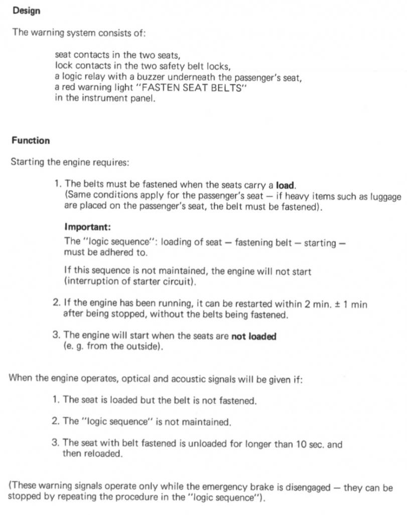 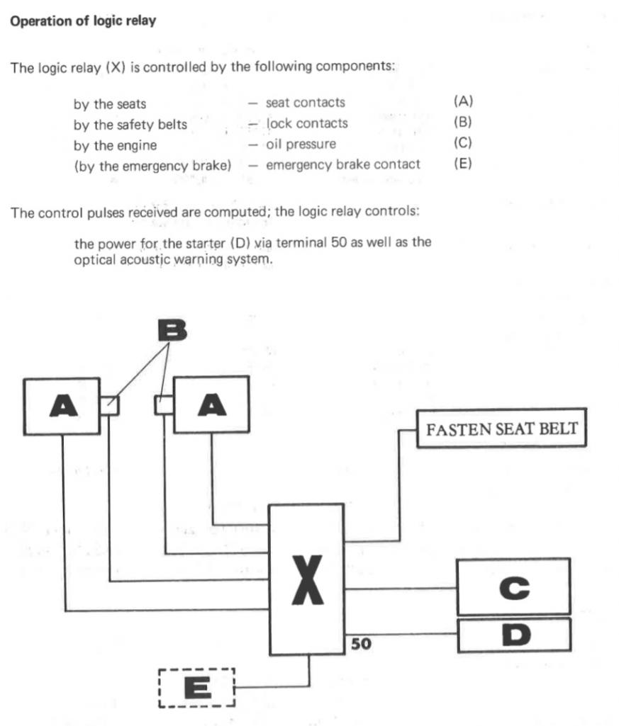 |
|
|
|
| ClayPerrine |
May 15 2025, 11:09 AM
Post
#4
|
|
Life's been good to me so far..... Group: Admin Posts: 16,542 Joined: 11-September 03 From: Hurst, TX. Member No.: 1,143 Region Association: NineFourteenerVille |
While I am curious to know how it works, I am still going to rip it and all the associated wiring for it out of the car.
I NEVER drive without a seatbelt. Number 1, it is stupid not to wear a seat belt. And Number 2, I am so conditioned to putting on the seat belt that I feel like I forgot my pants if I don't wear it. And nobody wants to see me without pants. (IMG:style_emoticons/default/w00t.gif) |
|
|
|
| Superhawk996 |
May 15 2025, 11:34 AM
Post
#5
|
|
914 Guru Group: Members Posts: 7,774 Joined: 25-August 18 From: Woods of N. Idaho Member No.: 22,428 Region Association: Galt's Gulch |
QUOTE(ClayPerrine @ May 15 2025, 01:09 PM)  While I am curious to know how it works, I am still going to rip it and all the associated wiring for it out of the car. Totally understand (IMG:style_emoticons/default/happy11.gif) |
|
|
|
| 914werke |
May 15 2025, 11:44 AM
Post
#6
|
|
"I got blisters on me fingers" Group: Members Posts: 11,620 Joined: 22-March 03 From: USofA Member No.: 453 Region Association: Pacific Northwest |
|
|
|
|
| Superhawk996 |
May 15 2025, 11:57 AM
Post
#7
|
|
914 Guru Group: Members Posts: 7,774 Joined: 25-August 18 From: Woods of N. Idaho Member No.: 22,428 Region Association: Galt's Gulch |
So this is where things start to go astray.
I cannot duplicate the “logic” operation of the training information. I have two different interlocks that appear to be functional. Neither seems to require that the seat cushion be loaded to enable the starter. I’ll detail this more later in the thread as it progresses. Second, I have been unable to verify that there is a time aspect as referenced for a restart within 2 minutes +/- 1 minute. There are 3 electrolytic capacitors in the circuit and it is possible that they are using a RC time constant to affect the circuit. I just haven’t been able to duplicate this and this is why I intend to put the circuit into LTSpice so I can better understand why this isn’t working as it is described by that training document. I am currently working on verify the capacitors. They are 50 years old and although they measure at their rated capacitance, they seem to leak a little more current than they should. [5/16/25 update - I’ve replaced the 3 electrolytic’s in the best operational relay - still no change in being able to get a seat cushion dependency or a time dependency] The one thing I haven’t been able to find is a 74’ -76’ owners manual to see how the operation is described there. If anyone cares to post that it would be appreciated. From here on out I’ll be posting the actual results I’ve observed bench testing the two “functional” relays I have. |
|
|
|
| Superhawk996 |
May 15 2025, 11:59 AM
Post
#8
|
|
914 Guru Group: Members Posts: 7,774 Joined: 25-August 18 From: Woods of N. Idaho Member No.: 22,428 Region Association: Galt's Gulch |
QUOTE(914werke @ May 15 2025, 01:44 PM) Any joker can cut it out (IMG:style_emoticons/default/happy11.gif) |
|
|
|
| rjames |
May 15 2025, 12:53 PM
Post
#9
|
|
I'm made of metal Group: Members Posts: 4,447 Joined: 24-July 05 From: Shoreline, WA Member No.: 4,467 Region Association: Pacific Northwest |
Following
(IMG:style_emoticons/default/popcorn[1].gif) I've thought about trying to reconnect it my '75 (was disconnected by the PO) just to see if it still works. I could do without a buzzer, but I think it would be kind of cool in a '70s sort of way to have the fasten belts sign light up with weight on the seat. |
|
|
|
| Root_Werks |
May 15 2025, 01:06 PM
Post
#10
|
|
Village Idiot Group: Members Posts: 8,932 Joined: 25-May 04 From: About 5NM from Canada Member No.: 2,105 Region Association: Pacific Northwest |
QUOTE(rjames @ May 15 2025, 11:53 AM) Following (IMG:style_emoticons/default/popcorn[1].gif) I've thought about trying to reconnect it my '75 (was disconnected by the PO) just to see if it still works. I could do without a buzzer, but I think it would be kind of cool in a '70s sort of way to have the fasten belts sign light up with weight on the seat. (IMG:style_emoticons/default/agree.gif) My 75' was already hacked up in a bad way. Wound up removing all the wires associated with the system including the ones up to the belt lock (replaced the stickers, why not?). Would be sort of cool to have it functional. That old school 70's buzzer. (IMG:style_emoticons/default/happy11.gif) |
|
|
|
| Superhawk996 |
May 15 2025, 02:47 PM
Post
#11
|
|
914 Guru Group: Members Posts: 7,774 Joined: 25-August 18 From: Woods of N. Idaho Member No.: 22,428 Region Association: Galt's Gulch |
Let’s start with the Haynes / factory manual black box & current flow diagram. This is useful to explain the basic wiring and switch states.
The bench testing will be set up with the following color code: Ground will be black. 12v power will be red Switched grounds will be green 12v starter power to the solenoid is yellow These are highlighted in the graphic below Driver door only shown as switched ground in green Door switches omitted - more on that later. 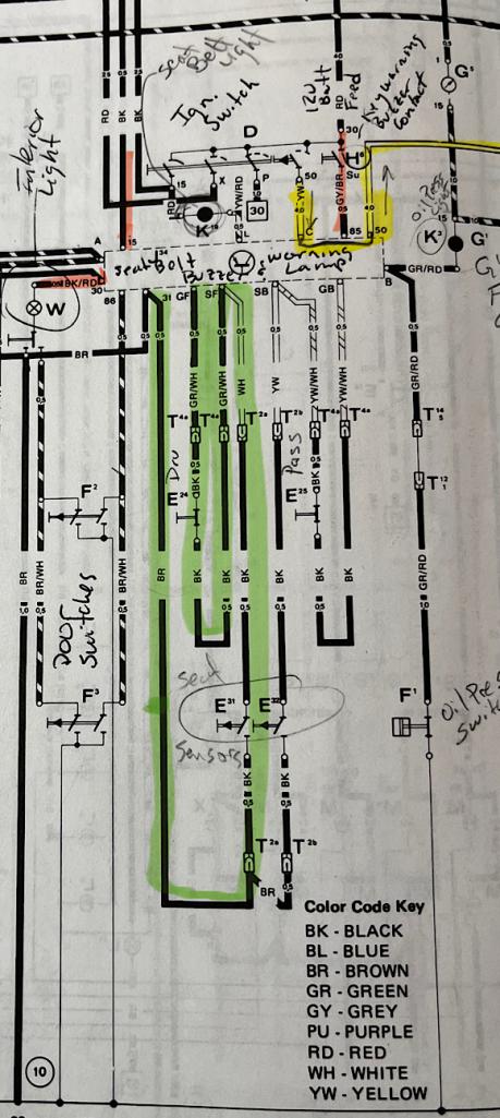 Power enters on pins: 15, 30, 85 Ground is pin 31 Yellow Pins “C” and 50 are the connections that are normally jumpers together when this system is disabled. The connection between these pins is normally completed inside the interlock relay when the seat belts have been fastened and the key is in the START position. |
|
|
|
| Superhawk996 |
May 15 2025, 02:59 PM
Post
#12
|
|
914 Guru Group: Members Posts: 7,774 Joined: 25-August 18 From: Woods of N. Idaho Member No.: 22,428 Region Association: Galt's Gulch |
The PIN ID’s are clearly labeled on the interlock relay.
Here’s the basic power and ground 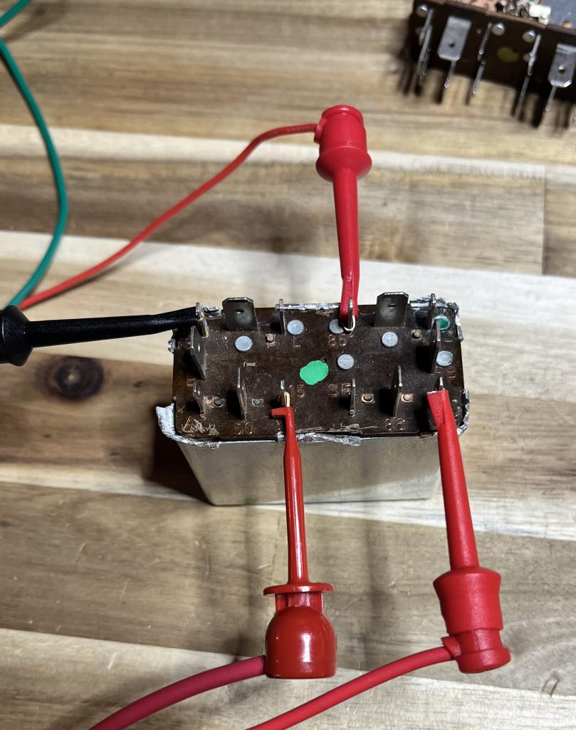 |
|
|
|
| Superhawk996 |
May 15 2025, 03:03 PM
Post
#13
|
|
914 Guru Group: Members Posts: 7,774 Joined: 25-August 18 From: Woods of N. Idaho Member No.: 22,428 Region Association: Galt's Gulch |
The Fasten Seat Belt light is powered by 12v supplied to one side of the bulb
The light is turned on/off via switched ground coming from the interlock relay on pin “L”, 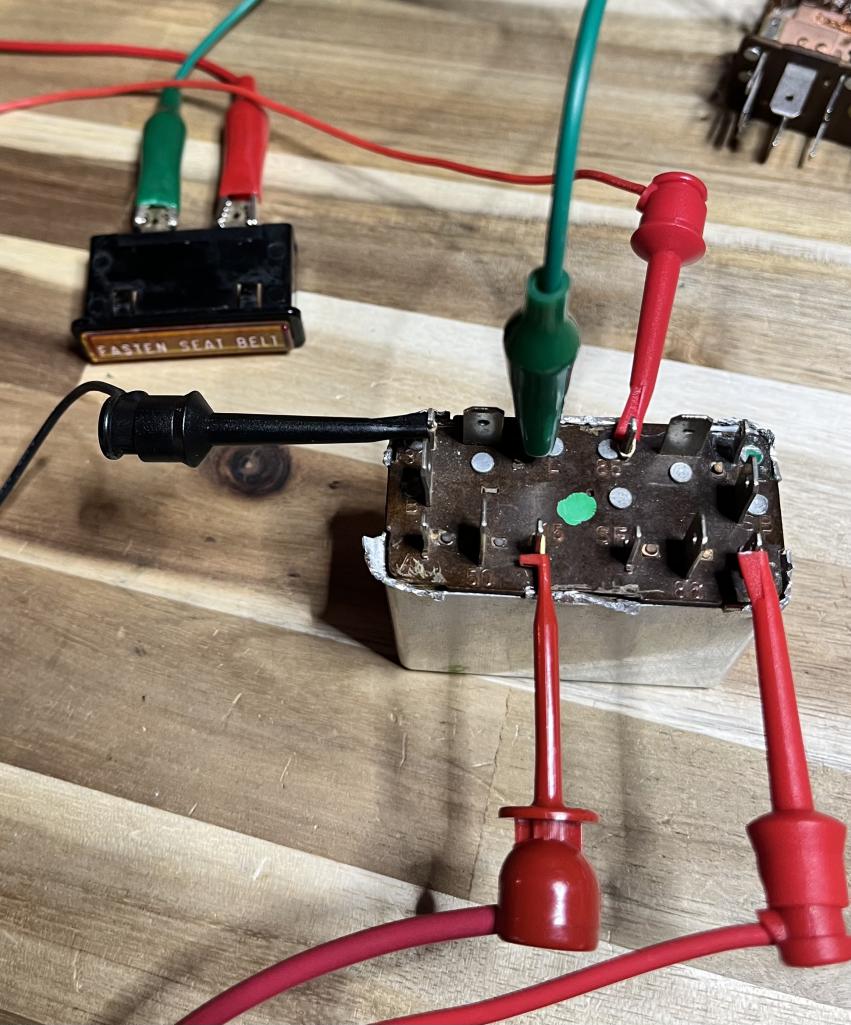 In the photo above you’ll notice that with no inputs from the seat cushions and no input from the seat belt latch switches - the Fasten Seat Belt (let’s abbreviate as FSB) light is not lit. The buzzer is not active. This setup represents: Key in ignition - 12v on pin 85 Ignition on - 12v on pin 15 and 30 Doors closed - no ground connection on pin 86 |
|
|
|
| Superhawk996 |
May 15 2025, 03:39 PM
Post
#14
|
|
914 Guru Group: Members Posts: 7,774 Joined: 25-August 18 From: Woods of N. Idaho Member No.: 22,428 Region Association: Galt's Gulch |
So let’s talk about the horrific buzzer
If a switched ground is addd to pin 86 representing an open door the buzzer will start screeching. This is shown in the video as the green switched ground wire contacting pin 86. When the door is closed, the switched ground is removed from pin 86 and the buzzing related to the key in ignition is silenced. The other way the buzzer can be silenced when the door is open is to remove the key from the ignition. When the key is removed, 12v power will be removed from pin 85. This is shown in the video as removal of the red 12v power from pin 85. This is the schematic: 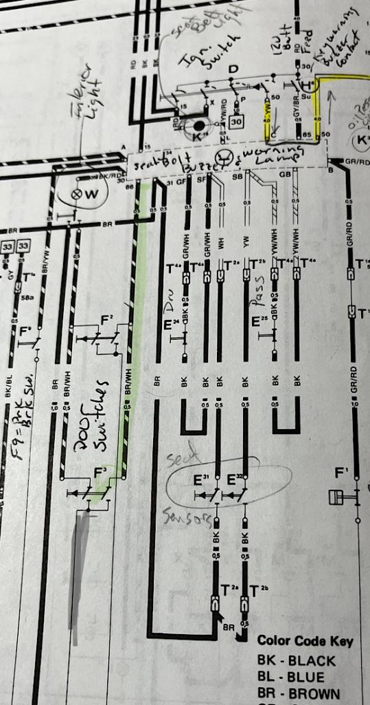 https://www.youtube.com/watch?v=XaIyrzDqc9A?si=LNyjKM6TgSI4igj Note: disregard the yellow starter circuit - I color in my books like a kid and unfortunately that is on the page and not a digital edit (IMG:style_emoticons/default/rolleyes.gif) |
|
|
|
| fiacra |
May 15 2025, 04:51 PM
Post
#15
|
|
Person.Woman.Man.Camera.TV. = MCI Group: Members Posts: 714 Joined: 1-March 19 From: East Bay Region - California Member No.: 22,920 Region Association: Northern California |
QUOTE(Superhawk996 @ May 15 2025, 10:57 AM) The one thing I haven’t been able to find is a 74’ -76’ owners manual to see how the operation is described there. If anyone cares to post that it would be appreciated. Here you go. From my 1975 Owner's manual. Page 26 simply talks about seat position and how to properly deploy the seat belt and isn't really relevant.   |
|
|
|
| rjames |
May 15 2025, 06:01 PM
Post
#16
|
|
I'm made of metal Group: Members Posts: 4,447 Joined: 24-July 05 From: Shoreline, WA Member No.: 4,467 Region Association: Pacific Northwest |
F that buzzer. (IMG:style_emoticons/default/laugh.gif)
|
|
|
|
| Superhawk996 |
May 15 2025, 06:38 PM
Post
#17
|
|
914 Guru Group: Members Posts: 7,774 Joined: 25-August 18 From: Woods of N. Idaho Member No.: 22,428 Region Association: Galt's Gulch |
QUOTE(rjames @ May 15 2025, 08:01 PM) (IMG:style_emoticons/default/lol-2.gif) for sure! I’ll have solutions for this later More stuff coming. I don’t have time to post it all in one giant chunk. Tomorrow I’ll cover the seat cushion and door switch behaviors. (IMG:style_emoticons/default/laugh.gif) |
|
|
|
| Superhawk996 |
May 15 2025, 06:52 PM
Post
#18
|
|
914 Guru Group: Members Posts: 7,774 Joined: 25-August 18 From: Woods of N. Idaho Member No.: 22,428 Region Association: Galt's Gulch |
QUOTE(fiacra @ May 15 2025, 06:51 PM) Here you go. From my 1975 Owner's manual. Thank you !! Was searching online and couldn’t find a copy - so sort of saying the same things as the training document. I will try to layout how this is true at least in part via the schematic if not explicitly by the functionality and bench test of the interlock relay. |
|
|
|
| Artfrombama |
May 15 2025, 07:05 PM
Post
#19
|
|
Artfrombama Group: Members Posts: 445 Joined: 21-January 24 From: One of the chosen few Member No.: 27,870 Region Association: South East States |
Interesting, appreciate the research!
P. O. did the jumper modification but the buzzer still works on my car, I ignore it. I left all the hardware in as well as the seat sensors in case the next owner(s) want to restore the thing. |
|
|
|
| JeffBowlsby |
May 15 2025, 09:51 PM
Post
#20
|
|
914 Wiring Harnesses & Beekeeper Group: Members Posts: 9,230 Joined: 7-January 03 From: San Ramon CA Member No.: 104 Region Association: None |
This is awesome Phil! Chipping away at one of the last 914 mysteries. Following.
|
|
|
|
|
1 User(s) are reading this topic (1 Guests and 0 Anonymous Users)
0 Members:

|
Lo-Fi Version | Time is now: 10th April 2026 - 03:06 AM |
Invision Power Board
v9.1.4 © 2026 IPS, Inc.