|
|
|
Porsche, and the Porsche crest are registered trademarks of Dr. Ing. h.c. F. Porsche AG.
This site is not affiliated with Porsche in any way. Its only purpose is to provide an online forum for car enthusiasts. All other trademarks are property of their respective owners. |
|
|

  |

| McMark |
 Jan 12 2006, 10:19 PM Jan 12 2006, 10:19 PM
Post
#1
|
||
|
914 Freak!  Group: Retired Admin Posts: 20,180 Joined: 13-March 03 From: Grand Rapids, MI Member No.: 419 Region Association: None |
I'm rebuilding a 57 bug with the original AM radio. I'm interested in the feasibility of an AM transmitter for an iPod. I found this circuit and description, but it's over my head. Could this be made small enough to be portable?
BTW, I'm familiar with FM transmitters and cassette adapters and radios hidden in the glovebox, etc. I'm not interested in anything else. Just AM transmitters. (IMG:http://www.914world.com/bbs2/html/emoticons/wink.gif)
Attached image(s) 
|
||
   |

 
|
||
| mightyohm |
Jan 12 2006, 10:31 PM
Post
#2
|
|
Advanced Member Group: Benefactors Posts: 2,277 Joined: 16-January 03 From: Seattle, WA Member No.: 162 Region Association: Pacific Northwest |
Looks doable. The hardest part is winding the coils for the inductors unless you can find them premade.
Overall the circuit will be pretty small except for the 140uH inductor and the antenna, which you could probably make into a coil. The fidelity will probably be pretty poor and you may have to retune the radio to follow the transmitter since open loop circuits like that tend to drift. If you picked one frequency to operate at and used a crystal it would be better. The frequency also tends to be "pushed" by nearby metal objects etc. You will also have to fight ignition noise, I don't see much filtering on that circuit and it is probably intended to operate with batteries. Here's a kit that is equally simple, but you won't have to wind your own inductors. http://www.ramseyelectronics.com/cgi-bin/c...action&key=AM1C There may be AM transmitter IC's around. I would think you could make the thing the size of an altoids box with a more modern circuit design. This kit uses a better approach: http://www.ramseyelectronics.com/cgi-bin/c...action&key=AM25 |
|
|
|
| 914GT |
Jan 12 2006, 10:52 PM
Post
#3
|
|
Senior Member Group: Members Posts: 1,101 Joined: 11-October 04 From: Tucson Member No.: 2,923 Region Association: Southwest Region |
Just AC couple the audio from the iPod into the volume control of the AM radio. You might need to switch out the antenna if outside signals interfere with the sound quality.
|
|
|
|
| McMark |
Jan 12 2006, 10:53 PM
Post
#4
|
|
914 Freak! Group: Retired Admin Posts: 20,180 Joined: 13-March 03 From: Grand Rapids, MI Member No.: 419 Region Association: None |
Hmmmm.... but is the volume control pre or post amp?
|
|
|
|
| 914GT |
Jan 12 2006, 10:55 PM
Post
#5
|
||
|
Senior Member Group: Members Posts: 1,101 Joined: 11-October 04 From: Tucson Member No.: 2,923 Region Association: Southwest Region |
Usually it's in the preamp section. |
||
|
|
|
||
| McMark |
Jan 12 2006, 11:08 PM
Post
#6
|
|
914 Freak! Group: Retired Admin Posts: 20,180 Joined: 13-March 03 From: Grand Rapids, MI Member No.: 419 Region Association: None |
Now, which ones to tap into on the Pot? The three white ones connect up front, and the green cloth covered one connects on the back. (IMG:http://www.914world.com/bbs2/html/emoticons/confused24.gif)
|
|
|
|
| McMark |
Jan 12 2006, 11:08 PM
Post
#7
|
|
914 Freak! Group: Retired Admin Posts: 20,180 Joined: 13-March 03 From: Grand Rapids, MI Member No.: 419 Region Association: None |
Use your imagination, or this picture. (IMG:http://www.914world.com/bbs2/html/emoticons/pinch.gif)
Attached image(s) 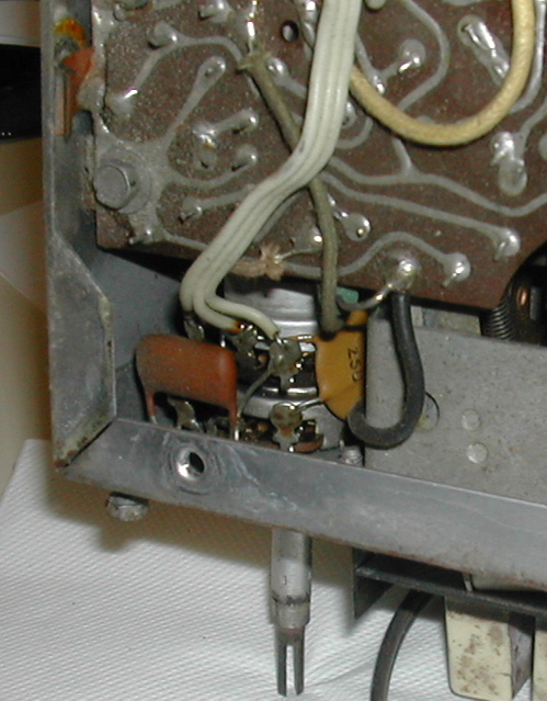
|
|
|
|
| McMark |
Jan 12 2006, 11:22 PM
Post
#8
|
|
914 Freak! Group: Retired Admin Posts: 20,180 Joined: 13-March 03 From: Grand Rapids, MI Member No.: 419 Region Association: None |
I just confirmed that the stereo does, in fact, work. So on to step 2. I'm off to Target to get a cheap headphone cord that I can cut and jack into the pot. (IMG:http://www.914world.com/bbs2/html/emoticons/smash.gif) You better have an answer for me by the time I get back. (IMG:http://www.914world.com/bbs2/html/emoticons/laugh.gif)
|
|
|
|
| 914GT |
Jan 12 2006, 11:23 PM
Post
#9
|
|
Senior Member Group: Members Posts: 1,101 Joined: 11-October 04 From: Tucson Member No.: 2,923 Region Association: Southwest Region |
Well, it's not exactly easy figuring out the wiring from the photo but I do see one end of the ganged pots connected through a ceramic disk cap. That might be a good place to try injecting an audio signal. One way to check it is to power the radio up to the speakers (leave the antenna unplugged) then touch your finger or a test lead to the terminals on the pots. Have the volume control up a ways, maybe halfway. If you hear buzzing or humming when you touch it, and can control the volume level of the noise, you've found a spot you can couple your external audio into. Assuming the radio is all transistors and 12V you won't get shocked. You can inject the external audio in through a capacitor (something like a 0.1 uF - 0.5 uF should be reasonable value). This will block any DC level from getting back into the iPod. If necessary an external resistor divider or trimmer pot could be used to set the level. You'll probably need to couple the iPod's left and right channels through a couple resistors anyway so you'll have a mono signal.
|
|
|
|
| McMark |
Jan 12 2006, 11:27 PM
Post
#10
|
|
914 Freak! Group: Retired Admin Posts: 20,180 Joined: 13-March 03 From: Grand Rapids, MI Member No.: 419 Region Association: None |
Will the signal and ground wires go to the pot? Or will the ground go to "chassis" ground (case) and the signal go to the pot?
|
|
|
|
| McMark |
Jan 13 2006, 12:18 AM
Post
#11
|
|
914 Freak! Group: Retired Admin Posts: 20,180 Joined: 13-March 03 From: Grand Rapids, MI Member No.: 419 Region Association: None |
Well I tried all the connection combos I could think of. But not sound. (IMG:http://www.914world.com/bbs2/html/emoticons/sad.gif)
Wait, what's this? I'm a moron? Yes, yes, that's it. A wire has come loose. I've found the wire and will be adding an audio in jack to this 1957 Bendix AM radio for iPod use. (IMG:http://www.914world.com/bbs2/html/emoticons/clap.gif) Thanks for the idea! I might even add a small 1W amp to boost the signal just a bit. (IMG:http://www.914world.com/bbs2/html/emoticons/idea.gif) Now to deal with the scratchy pot. (IMG:http://www.914world.com/bbs2/html/emoticons/wacko.gif) |
|
|
|
| mightyohm |
Jan 13 2006, 01:37 AM
Post
#12
|
|
Advanced Member Group: Benefactors Posts: 2,277 Joined: 16-January 03 From: Seattle, WA Member No.: 162 Region Association: Pacific Northwest |
That was fast. I'm impressed! (IMG:http://www.914world.com/bbs2/html/emoticons/biggrin.gif) Nice alternative solution!
|
|
|
|
| McMark |
Jan 13 2006, 02:06 AM
Post
#13
|
|
914 Freak! Group: Retired Admin Posts: 20,180 Joined: 13-March 03 From: Grand Rapids, MI Member No.: 419 Region Association: None |
New Question: I just found out the radio is 6 volt supposedly. Since it obviously works on 12 volt, what's going on? Electronics make me feel stupid. (IMG:http://www.914world.com/bbs2/html/emoticons/unsure.gif)
Is this one of those situations where it will work in the short term, but will probably die quickly? (IMG:http://www.914world.com/bbs2/html/emoticons/confused24.gif) Upon reading more I'm starting to wonder if this radio has been converted. The bulb didn't burn out as I've been led to believe a 6v bulb will when connected to 12v. (IMG:http://www.914world.com/bbs2/html/emoticons/wacko.gif) |
|
|
|
| 914GT |
Jan 13 2006, 08:50 AM
Post
#14
|
|
Senior Member Group: Members Posts: 1,101 Joined: 11-October 04 From: Tucson Member No.: 2,923 Region Association: Southwest Region |
Mark,
Usually something designed for a particular voltage will not last long if you double the voltage on it, especially if it's 'solid state' (haven't used that term in awhile). If the radio has 6V stamped on it and it's running on 12, it must have been modified and that would mean having a dropping resistor or regulator put in somewhere on the DC input. Dropping resistors are a poor way for a car radio since the load changes with music and volume level. If the bulbs in the radio are looking normal brightness it must be OK. On your earlier question - the shield or ground would connect to the chassis (I'm assuming this is a negative ground setup on the battery). Depending on how sophisticated you want to get with this, it should be possible to separate the preamp section from the AM tuner at the volume control. Then you could bring these out to a switch and have it selectable from AM radio to iPod input. Have fun! |
|
|
|
| KenH |
Jan 13 2006, 11:36 AM
Post
#15
|
|
Senior Member Group: Members Posts: 680 Joined: 16-January 03 From: Gilroy, CA Member No.: 156 |
Google this "am modulation IC" lots of circuits are listed.
Ken |
|
|
|
| Eddie Williams |
Jan 13 2006, 11:52 AM
Post
#16
|
|
Senior Member Group: Members Posts: 822 Joined: 30-December 02 From: Nederland, TX Member No.: 55 Region Association: None |
Wow an iPod in a 50 year old Bug with the original 6volt AM radio.... Who'd of thunk it?
I love this site!!! (IMG:http://www.914world.com/bbs2/html/emoticons/wub.gif) |
|
|
|
|
1 User(s) are reading this topic (1 Guests and 0 Anonymous Users)
0 Members:

|
Lo-Fi Version | Time is now: 4th July 2025 - 08:40 AM |
Invision Power Board
v9.1.4 © 2025 IPS, Inc.