|
|
|
Porsche, and the Porsche crest are registered trademarks of Dr. Ing. h.c. F. Porsche AG.
This site is not affiliated with Porsche in any way. Its only purpose is to provide an online forum for car enthusiasts. All other trademarks are property of their respective owners. |
|
|

  |

| mrdezyne |
 Jun 21 2006, 10:14 AM Jun 21 2006, 10:14 AM
Post
#1
|
|
Now on larger rolling jack stands!  Group: Members Posts: 468 Joined: 31-July 05 From: Tulsa, OK Member No.: 4,510 |
Lots of good info out there on cable shifters for the 901 and 930 transaxles. I've been trying to keep up with most of them, but I'm having trouble visualizing what has to happen at the tail end of a side shift 901. I've seen several brackets and how the cables are connected but I still don't have a clear picture. Can someone in the know help provide a little insight? Please use small words and lots of pictures.... (IMG:style_emoticons/default/blink.gif)
Let cable shift 101 begin.... |
   |

 
|
| Jeroen |
Jun 21 2006, 10:21 AM
Post
#2
|
|
914 Guru Group: Members Posts: 7,887 Joined: 24-December 02 From: The Netherlands Member No.: 3 Region Association: Europe |
|
|
|
|
| TonyAKAVW |
Jun 21 2006, 10:28 AM
Post
#3
|
|
That's my ride. Group: Members Posts: 2,151 Joined: 17-January 03 From: Redondo Beach, CA Member No.: 166 Region Association: None |
There are two movements that need to happen. The shaft on the transmission needs to be pushed in or out to select the pairs of gears, (1-R), (2-3), (4-5) and then the shaft must be rotated clockwise or counter-clockwise to select the actual gear (1,2,3,4,5,R).
So the cable shifter needs to translate the push/pull action of a pair of cables into a rotational motion and a push/pull motion that is probably perpendicular to the way the cable is connected to the transmission. To complicate things, both motions need to happen without largely affecting one another. That is to say that the rotational motion part cannot interfere with the operation of the push/pull part and vice-versa. The simplest motion to implement is the rotational. Simply put a lever arm on the shaft and connect the cable to the far end. In the diagram, the rotational action is shown without the in/out action. The in/out action is a bit harder to implement because the cable that is responsible for that action must be able to push or pull the shift rod while it is simultaneously rotating. In the case of Bondo's shifter, he uses a lever so that the push-pull cable can enter the assembly from the top. There is no room under the car for a cable to enter unless you are going with a high ride-height. -Tony Attached image(s) 
|
|
|
|
| Dave_Darling |
Jun 21 2006, 10:34 AM
Post
#4
|
|
914 Idiot Group: Members Posts: 15,203 Joined: 9-January 03 From: Silicon Valley / Kailua-Kona Member No.: 121 Region Association: Northern California |
You need two cables, both of which are push-pull cables (they push on the moving bits as well as pull on them). One cable has to pull the thing that comes out of the transmission forward-and aft. That gives you the same movement as moving the gear shift forward and aft.
The other cable has to move the thing that comes out of the transmission in and out of the transmission case. That gives you the same movement as moving the gear shift lever left and right. If you unhook the gear shift linkage from the transmission, you'll see what I mean about the movement. The part that sticks into the transmission can be slid in and out, and the knob end of it can be moved fore and aft. What you have to do with the cables is set them up so that each cable moves that part in the correct direction. That's easy for the fore-and-aft part, but the in-and-out movement is tougher to do. That's mostly because the motion you're trying to make goes left and down, so the cable would have to run left and down--and it would probably get very close to the ground! If you want to avoid this (which you probably do, because it would suck to have a rock or piece of debris take out your shifter!) then you have to set up some other way of converting a cable push and pull motion to a gear selector thingie sliding in and out motion. Which is where it gets complicated... It's actually easier, I believe, on a tail-shifter. The sliding in and out actually goes straight out to the side, which means the cable doesn't have to go close to the ground. --DD |
|
|
|
| TonyAKAVW |
Jun 21 2006, 10:36 AM
Post
#5
|
|
That's my ride. Group: Members Posts: 2,151 Joined: 17-January 03 From: Redondo Beach, CA Member No.: 166 Region Association: None |
In this picture (my prototype shifter) you can see there are two threaded rods. These threaded rods are where the cable ends attach. The one in the distance at the top is for the rotational motion. If you pull or push that lever left or right it will rotate the shaft (which is going straight down through the aluminum plate into the transmission).
The other motion is accomplished by pushing or pulling the threaded rod that has the two nuts on it. If that is pushed left or right it forces the white plastic block to move up and down. That forces the selector to pull out or push into the transmission. In the second picture you can see thethreaded rod that in the first picture is at the top, and kind of blurry. Sorry for the SirAndy style photo (IMG:style_emoticons/default/smile.gif) -Tony Attached image(s) 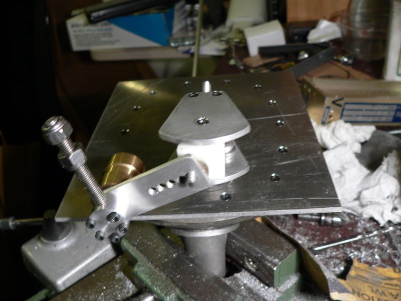 
|
|
|
|
| mrdezyne |
Jun 21 2006, 10:47 AM
Post
#6
|
|
Now on larger rolling jack stands! Group: Members Posts: 468 Joined: 31-July 05 From: Tulsa, OK Member No.: 4,510 |
So the brass bearing is supposed to be attached to the plate so that the movment is translated through to the delrin block?
|
|
|
|
| lapuwali |
Jun 21 2006, 10:53 AM
Post
#7
|
|
Not another one! Group: Benefactors Posts: 4,526 Joined: 1-March 04 From: San Mateo, CA Member No.: 1,743 |
bondo has a thread here with his super-slick setup, using an animated image to show the motions in steps.
|
|
|
|
| TonyAKAVW |
Jun 21 2006, 10:59 AM
Post
#8
|
|
That's my ride. Group: Members Posts: 2,151 Joined: 17-January 03 From: Redondo Beach, CA Member No.: 166 Region Association: None |
QUOTE(mrdezyne @ Jun 21 2006, 09:47 AM)  So the brass bearing is supposed to be attached to the plate so that the movment is translated through to the delrin block? yes, exactly! |
|
|
|
| mrdezyne |
Jun 21 2006, 11:24 AM
Post
#9
|
|
Now on larger rolling jack stands! Group: Members Posts: 468 Joined: 31-July 05 From: Tulsa, OK Member No.: 4,510 |
Thanks Tony! Maybe when you are finished with your prototype I can borrow it to nail down the specific dimensions and throw distances. I just took a look through Bondo's thread and that is a freakin work of art!
Things are starting to click and the squeaky wheels are starting to turn again. Thanks for the input. I know this is a pretty hot topic right now with several people developing cable shifters at the same time. If anyone has other info they would like to add please chime in! |
|
|
|
|
1 User(s) are reading this topic (1 Guests and 0 Anonymous Users)
0 Members:

|
Lo-Fi Version | Time is now: 13th July 2025 - 07:50 PM |
Invision Power Board
v9.1.4 © 2025 IPS, Inc.