|
|
|
Porsche, and the Porsche crest are registered trademarks of Dr. Ing. h.c. F. Porsche AG.
This site is not affiliated with Porsche in any way. Its only purpose is to provide an online forum for car enthusiasts. All other trademarks are property of their respective owners. |
|
|


| rwilner |
 May 29 2012, 08:49 AM May 29 2012, 08:49 AM
Post
#1
|
|
No Ghosts in the Machine  Group: Members Posts: 953 Joined: 30-March 10 From: Boston, MA Member No.: 11,530 Region Association: North East States |
I was told this engine came from a 1.7 that was in a 914. I'm tearing it down to rebuild into a 2056.
First, I found an M12 or M14 triple square bolt with a spring under it. This bolt is located between two pushrod tubes. I'm guessing this is the oil pressure relief since I didn't find the giant slotted plug I was expecting to find...true? Second, there is no windage tray. Did the early motors not have a windage tray? Should I source one and install it? I don't see anyplace in the casting that would receive the tray... Third, I didn't find the serial number where I expected it to be -- in front of the breather tower. Where else could it be? It seems like a low mile case to me...lifters and cam bearings show minimal wear, the cam looks to even be reusable to my untrained eye. If I had to guess i'd say this was a low-mile motor that got parked due to FI problems or something. have no pics but will post some tonight. |
   |

 
|
  |
Replies(1 - 19)
| r_towle |
May 29 2012, 08:53 AM
Post
#2
|
|
Custom Member Group: Members Posts: 24,585 Joined: 9-January 03 From: Taxachusetts Member No.: 124 Region Association: North East States |
the large bolt is an oil releif valve.
Not sure about the windage tray...how do you get oil out of the sump to the oil pump? Is the tube there? Serial number is on top of the case, near the split. only 2.0 liter had the number on the tower. rich |
|
|
|
| rwilner |
May 29 2012, 09:28 AM
Post
#3
|
|
No Ghosts in the Machine Group: Members Posts: 953 Joined: 30-March 10 From: Boston, MA Member No.: 11,530 Region Association: North East States |
QUOTE(r_towle @ May 29 2012, 10:53 AM)  Not sure about the windage tray...how do you get oil out of the sump to the oil pump? The oil pickup is there (green box), but the tray is not (red box). Picture courtesy of Van Svenson! (thanks van) 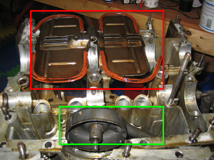 |
|
|
|
| r_towle |
May 29 2012, 09:37 AM
Post
#4
|
|
Custom Member Group: Members Posts: 24,585 Joined: 9-January 03 From: Taxachusetts Member No.: 124 Region Association: North East States |
windage tray is not required...just keeps the oil from sloshing around under heavy g-force. Also keeps it from getting whipped up.
Its a good idea, but not required. Rich |
|
|
|
| McMark |
May 29 2012, 09:45 AM
Post
#5
|
|
914 Freak! Group: Retired Admin Posts: 20,179 Joined: 13-March 03 From: Grand Rapids, MI Member No.: 419 Region Association: None |
The triple square bolt is the second oil pressure relief. The first one is on the bottom of the engine, under the oil filter mount. Some later cases don't have the second valve, but all have the first one. Buy a drag link socket for the screw driver head on the first one. And use a 3/8" extension (no socket, just the extention) on the triple square head of the second one.
(IMG:http://www.914world.com/bbs2/uploads_offsite/www.practicalmachinist.com-419-1338306306.1.jpg) Not all engines had the windage tray. I've never heard a definitive reason for why they were put in or not. And it's been debated as to if they should be put back in. They can help control windage (s the name implies) but it's also been speculated that they might impede oil flow back into the sump. The pushrod tubes dump their oil on top of the tray, and the oil must make it's way back down to the sump. This also deposits oil near the spinning crank, which is how windage happens. One modification used in the past is to drill holes in the tray just underneath the semi-rectangular openings on the bottom of the lifter bores. This is where the oil returns from the head, and by opening up these areas you can accelerate flow back into the sump. Here's a picture - these openings are from a very early engine and aren't located where I would put them now. 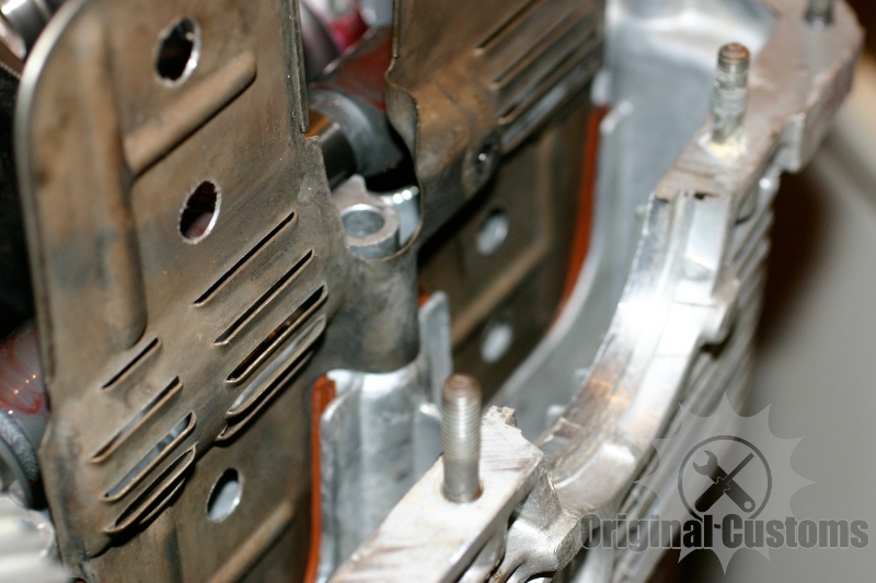 Serial numbers for non 914-2.0 engines are near the flywheel on a 45-degree flat section. |
|
|
|
| rwilner |
May 29 2012, 11:54 AM
Post
#6
|
|
No Ghosts in the Machine Group: Members Posts: 953 Joined: 30-March 10 From: Boston, MA Member No.: 11,530 Region Association: North East States |
Thanks mark...never even heard of a drag link socket before.
Off to sears! |
|
|
|
| Cap'n Krusty |
May 29 2012, 12:05 PM
Post
#7
|
|
Cap'n Krusty Group: Members Posts: 10,794 Joined: 24-June 04 From: Santa Maria, CA Member No.: 2,246 Region Association: Central California |
Serial numbers: Early bus cases didn't have a number. It was located on the fan housing. An early bus case can be identified by the oil filler passage next to the taco plate opening, the fuel pump flange being finished for use, and the lack of a dipstick tube on the top of the case.
If you add a windage tray, you'll need the tray, the four seals, and an oil pickup modified to allow attachment of the tray. The Cap'n |
|
|
|
| rwilner |
May 29 2012, 12:14 PM
Post
#8
|
|
No Ghosts in the Machine Group: Members Posts: 953 Joined: 30-March 10 From: Boston, MA Member No.: 11,530 Region Association: North East States |
QUOTE(Cap'n Krusty @ May 29 2012, 02:05 PM) Serial numbers: Early bus cases didn't have a number. It was located on the fan housing. An early bus case can be identified by the oil filler passage next to the taco plate opening, the fuel pump flange being finished for use, and the lack of a dipstick tube on the top of the case. based on this I do indeed have a 914 case, as the dipstick is on top of the case. QUOTE If you add a windage tray, you'll need the tray, the four seals, and an oil pickup modified to allow attachment of the tray. The Cap'n Is there anything special about the cases that came from the factory with the tray installed? In other words -- does the tray slip into some grooves that were cast into the later cases (which may be absent in my early 1.7 case)? |
|
|
|
| falconfp2001 |
May 29 2012, 12:24 PM
Post
#9
|
|
Pancho Pantera Group: Members Posts: 451 Joined: 5-December 10 From: Downey, CA Member No.: 12,456 Region Association: Southwest Region |
Hey Rich,
what's your plan for building the 2056? are you going to replace the crank with a 2.0 crank? I'm interested as I'd like to use my spare 1.7 for this also. thanks |
|
|
|
| pilothyer |
May 29 2012, 01:03 PM
Post
#10
|
|
Member Group: Members Posts: 838 Joined: 21-May 08 From: N. Alabama Member No.: 9,080 Region Association: South East States |
QUOTE(rwilner @ May 29 2012, 01:14 PM) Is there anything special about the cases that came from the factory with the tray installed? In other words -- does the tray slip into some grooves that were cast into the later cases (which may be absent in my early 1.7 case)? The early WO cases up untill 1972 didn't come with the oil baffle plate. They didn't even have the special ribs to install one until Engine # WO 074387 in 1971. The objective was to insure that the oil intake pipe remained submerged in oil during sharp cornering. |
|
|
|
| rwilner |
May 29 2012, 01:06 PM
Post
#11
|
|
No Ghosts in the Machine Group: Members Posts: 953 Joined: 30-March 10 From: Boston, MA Member No.: 11,530 Region Association: North East States |
QUOTE(falconfp2001 @ May 29 2012, 02:24 PM) Hey Rich, what's your plan for building the 2056? are you going to replace the crank with a 2.0 crank? I'm interested as I'd like to use my spare 1.7 for this also. thanks Yep. stock 2.0 crank, stock 2.0 rods rebuilt, arp fasteners, 1.8 cyls bored out to 96mm, and 96mm KB pistons is my plan. My understanding is that the 1.7 case will not require any clearancing with this combo but of course the mock-up will tell me what's what. I've also been told the 1.7 cases are the best for making big engines although I'm not sure why... |
|
|
|
| rwilner |
May 29 2012, 01:07 PM
Post
#12
|
|
No Ghosts in the Machine Group: Members Posts: 953 Joined: 30-March 10 From: Boston, MA Member No.: 11,530 Region Association: North East States |
QUOTE(pilothyer @ May 29 2012, 03:03 PM) They didn't even have the special ribs to install one until Engine # WO 074387 in 1971. I have no idea how you know this but that is a pretty impressive piece of trivia. I'll find the serial number to see if my case has the ribs, and if so, source the baffle and pickup (or drill a hole in my pickup). |
|
|
|
| McMark |
May 29 2012, 01:09 PM
Post
#13
|
|
914 Freak! Group: Retired Admin Posts: 20,179 Joined: 13-March 03 From: Grand Rapids, MI Member No.: 419 Region Association: None |
The yellow arrows are the 'rib' that holds the tray. If your case doesn't have this, you can't use a tray. (BTW, if you need one, let me know. I have tons)
The purple arrows are the previously mentioned pushrod tube drains. If you want to add holes, do it under these guys. Attached image(s) 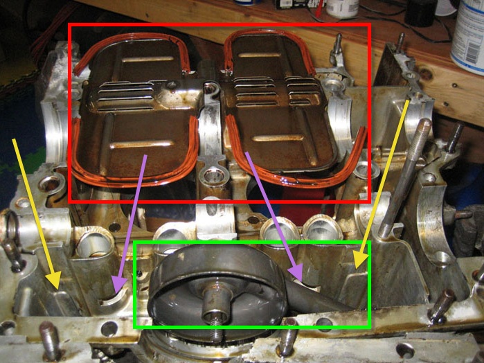
|
|
|
|
| falconfp2001 |
May 29 2012, 01:14 PM
Post
#14
|
|
Pancho Pantera Group: Members Posts: 451 Joined: 5-December 10 From: Downey, CA Member No.: 12,456 Region Association: Southwest Region |
QUOTE(rwilner @ May 29 2012, 12:06 PM) QUOTE(falconfp2001 @ May 29 2012, 02:24 PM) Hey Rich, what's your plan for building the 2056? are you going to replace the crank with a 2.0 crank? I'm interested as I'd like to use my spare 1.7 for this also. thanks Yep. stock 2.0 crank, stock 2.0 rods rebuilt, arp fasteners, 1.8 cyls bored out to 96mm, and 96mm KB pistons is my plan. My understanding is that the 1.7 case will not require any clearancing with this combo but of course the mock-up will tell me what's what. I've also been told the 1.7 cases are the best for making big engines although I'm not sure why... Maybe they are better due to less stress. I don't really get on the gas in my 1.7 but if I had a 2056 with a Dr. Evil Transmission, I'd be all over it. |
|
|
|
| Valy |
May 29 2012, 01:15 PM
Post
#15
|
|
Senior Member Group: Members Posts: 1,677 Joined: 6-April 10 From: Sunnyvale, CA Member No.: 11,573 Region Association: Northern California |
(IMG:style_emoticons/default/thisthreadisworthlesswithoutpics.gif)
You got pretty much all the answers already so not going to repeat them. If you decide to add a windage tray take a look at my build (in my signature) and make sure the oil pick-up length stays the same length as your original pickup. In my opinion, the tray helps keeping some oil close to the crank to be splashed on the cylinders and pistons for cooling. It also keeps the oil foam there that's easier to be thrown on the cylinders. The hot oil is very liquid and will go down in the sump quite fast. The serial number should be either in front of the oil breather or on top of the case above cylinder #3. You may also have a replacement case that has no S/N. I have one that was stamped by some shop with a new SN. Post a picture of the cam and lifters. They might look OK but rarely are. Measure the cam lift (diameter across the lobe less the diameter at 90deg). You should get 7.677mm and 7.192mm for the stock cam. Check the top of the lobe for a small depression. If you see it, the cam is dead (There is a picture in my rebuilt). That depression is caused by the lifters pressing on the sides of the lobe and those forces concentrating below the surface of the lobe, in its middle. The metal is compressed there and the sealing collapses creating the small depression. Take two lifters and mat their faces. They should rock a bit as the faces are a bit like this )( . You can look at them against a light source and see light passing on the sides. If they are flat or like this (), you need new ones. Hope it helps. |
|
|
|
| rwilner |
May 29 2012, 05:31 PM
Post
#16
|
|
No Ghosts in the Machine Group: Members Posts: 953 Joined: 30-March 10 From: Boston, MA Member No.: 11,530 Region Association: North East States |
Hey Valy
The only stuff I'm planning to reuse is the case and small bits -- the rest of it will be either brand new or remanufactured. Also...looks like I DO have the ribs for the windage tray, so I'll be looking to source one of those and a pickup to go along with it. Here's case half #1: (IMG:http://www.914world.com/bbs2/uploads_offsite/lh4.googleusercontent.com-11530-1338334258.1.JPG) Case half #2: (IMG:http://www.914world.com/bbs2/uploads_offsite/lh6.googleusercontent.com-11530-1338334259.2.JPG) The case mating surface looked good all the way around except for this area at the top, I think it will be fine but what do you guys think? (IMG:http://www.914world.com/bbs2/uploads_offsite/lh3.googleusercontent.com-11530-1338334260.3.JPG) Here's the crank: (IMG:http://www.914world.com/bbs2/uploads_offsite/lh3.googleusercontent.com-11530-1338334261.4.JPG) And the cam: (IMG:http://www.914world.com/bbs2/uploads_offsite/lh4.googleusercontent.com-11530-1338334261.5.JPG) There is some wear on one lobe. This was the only wear I could easily see: (IMG:http://www.914world.com/bbs2/uploads_offsite/lh4.googleusercontent.com-11530-1338334261.6.JPG) And, the serial number...this is the only clean part of the case: (IMG:http://www.914world.com/bbs2/uploads_offsite/lh5.googleusercontent.com-11530-1338334306.1.JPG) Time to clean, clean, and clean some more. |
|
|
|
| Valy |
May 29 2012, 05:54 PM
Post
#17
|
|
Senior Member Group: Members Posts: 1,677 Joined: 6-April 10 From: Sunnyvale, CA Member No.: 11,573 Region Association: Northern California |
1. Take the dowel pins out now and keep them safe.
2. Make sure you got the dizzy drive special washer out too. Keep it safe as well as it's a PITA to look for it in a pile of bolts and washers. 3. This deformation in the case matting surface seems not important to me. 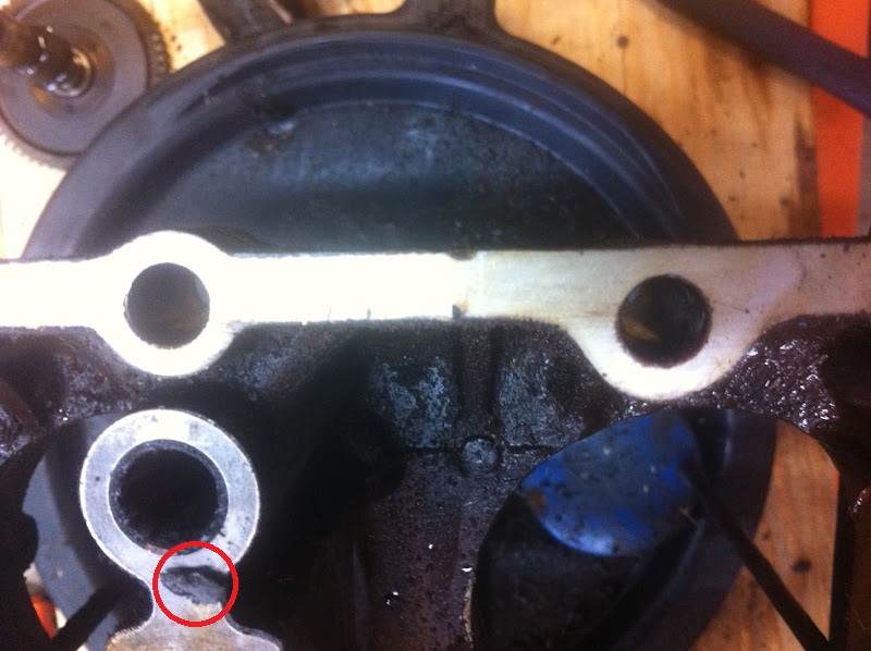 4. The cam is toast. Here is the depression I was talking about. If the gear is good (they usually are) keep it. You just need to cut it a bit in the middle to make place for the bolts. It's usually cheaper then just a new cam gear. 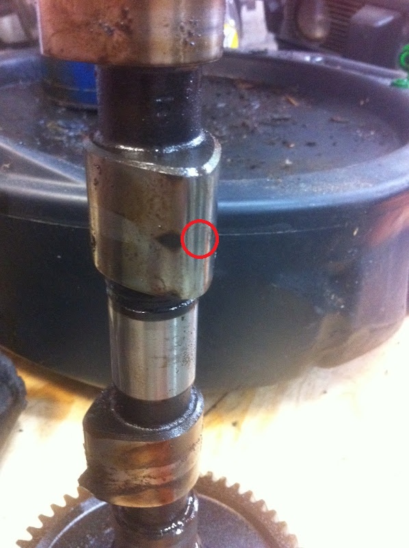 5. I can see you have the slots for the windage tray. 6. I don't like the color on the bearings. Is it just dirt or burn marks? 7. Check the bearing external size to see where you are. STD big bearings should be 60.0mm and the nose bearing should be 40.0mm. Next step is 60.5mm and 61mm but the later are very rare. If you need, I know a source but maybe a different case will be cheaper. I would not bother too much cleaning the case. Send it to the shop and after a run in the parts cleaner will make it cleaner than you'll have it after a week of work. They will clean it anyway as you just can't clean all that stuff. |
|
|
|
| Harpo |
May 29 2012, 06:54 PM
Post
#18
|
|
Senior Member Group: Members Posts: 1,304 Joined: 21-August 11 From: Motor City aka Detroit Member No.: 13,469 Region Association: None |
You mentioned that you will be using ARP fasteners. Will you be using the head studs and the through bolts.
Thanks David |
|
|
|
| rwilner |
May 29 2012, 07:31 PM
Post
#19
|
|
No Ghosts in the Machine Group: Members Posts: 953 Joined: 30-March 10 From: Boston, MA Member No.: 11,530 Region Association: North East States |
QUOTE(Harpo @ May 29 2012, 08:54 PM) You mentioned that you will be using ARP fasteners. Will you be using the head studs and the through bolts. Thanks David From what I've read...(this is my first build) The Arp head studs and through bolts are only an advantage if youre going to nickies. Some things I read indicate that the arp head studs and through bolts have some compatibility issues with stock cylinders due to expansion characteristics, but who knows... I will be using the arp fasteners on reconditioned stock 2.0 rods and stock head studs and through bolts. |
|
|
|
| rwilner |
May 30 2012, 05:52 AM
Post
#20
|
|
No Ghosts in the Machine Group: Members Posts: 953 Joined: 30-March 10 From: Boston, MA Member No.: 11,530 Region Association: North East States |
Valy -- just read your thread and saw the part about the windage tray and pickup -- great info, looks like exactly what I'll need to do.
thanks!! Rich |
|
|
|
|
1 User(s) are reading this topic (1 Guests and 0 Anonymous Users)
0 Members:

|
Lo-Fi Version | Time is now: 4th June 2024 - 08:07 PM |
Invision Power Board
v9.1.4 © 2024 IPS, Inc.