|
|
|
Porsche, and the Porsche crest are registered trademarks of Dr. Ing. h.c. F. Porsche AG.
This site is not affiliated with Porsche in any way. Its only purpose is to provide an online forum for car enthusiasts. All other trademarks are property of their respective owners. |
|
|


| malcolm2 |
 Dec 14 2013, 08:34 PM Dec 14 2013, 08:34 PM
Post
#1
|
|
Advanced Member  Group: Members Posts: 2,747 Joined: 31-May 11 From: Nashville Member No.: 13,139 Region Association: South East States |
The only thing installed on my car that is associated with HEAT would be the exchangers. Nothing else. I need to get the heat working so I started with the Heater fan in the engine bay.
SO FAR: successfully bench tested the fan with 12v. Put a known good headlight relay in the fan relay socket Successfully checked continuity of the wire from the lever to the 14-pin connector (GRN/wht). Connector attatched, and unattached Successfully checked continuity from the relay (87) to the fan (green wire), car was not running. Strange thing I noticed. Checking continuity from the lever to Pin #9 was good. I then checked continuity between the lever and pin 13, 11, 7, 5, 3, 2 & 1. With the 14-pin connector connected they all showed continuity to ground. THIS CAN"T BE RIGHT, can it? The car runs fine, all the lights work. Seems like a ground short, but it is not affecting anything else. My goal here was to (as designed) get 12v to the green wire on the fan, but I can't. I have read several posts that gave me some direction. But I am lost. Thanks, Clark 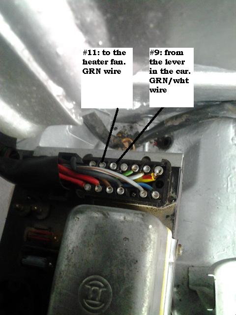 |
   |

 
|
  |
Replies(1 - 6)
| Dave_Darling |
Dec 14 2013, 11:50 PM
Post
#2
|
|
914 Idiot Group: Members Posts: 15,196 Joined: 9-January 03 From: Silicon Valley / Kailua-Kona Member No.: 121 Region Association: Northern California |
Not sure about the "continuity with everything" bit.
But here is how the heater blower circuit works: The switch on the bottom of the "DEFROST" lever gets grounded when you pull the lever up high enough. That grounds one of the control pins (85 or 86, forget which) of the heater blower relay, which sends power from #30 of the relay to #87 of the relay. That power is what runs the fan. Power gets to #30 of the relay through one of the fuses on the relay board. I don't remember how power gets to the other control pin of the relay, but it should be "switched power". --DD |
|
|
|
| etcmss |
Dec 15 2013, 06:15 AM
Post
#3
|
|
etcmss Group: Members Posts: 183 Joined: 20-April 06 From: Lancaster, Ky Member No.: 5,899 Region Association: Upper MidWest |
I've done this a couple of times and briefly remember just getting the 12 volts from pin 11 to the fan and it worked fine. if the lever arm switch is working through the relay then it should be ok.
|
|
|
|
| malcolm2 |
Dec 15 2013, 09:45 AM
Post
#4
|
|
Advanced Member Group: Members Posts: 2,747 Joined: 31-May 11 From: Nashville Member No.: 13,139 Region Association: South East States |
QUOTE(Dave_Darling @ Dec 14 2013, 11:50 PM)  But here is how the heater blower circuit works: The switch on the bottom of the "DEFROST" lever gets grounded when you pull the lever up high enough. That grounds one of the control pins (85 or 86, forget which) of the heater blower relay, which sends power from #30 of the relay to #87 of the relay. That power is what runs the fan. Power gets to #30 of the relay through one of the fuses on the relay board. I don't remember how power gets to the other control pin of the relay, but it should be "switched power". --DD Here is what I figured from the diagrams, etc.... The lever grounds pin 9 in the 12-pin connector, that goes to (grounds?) 86 in the relay and should change the state of the relay so 87 and 85 in the relay connect. 85 gets power from pin 7 in the 14-pin connector, pin 7 brings 12v from the coil. 87 then sends 12v to pin 11 that is jumped to pin 10 ( both on 12-pin conn). Pin 10 goes to pin 11 on the 12-pin connector, and that has the green wire to the fan. The fan is grounded with a brown wire. I will check all with the meter again. Nice design of the 12 & 14 pin connectors. Just remove the cap and everything can be tested. (IMG:style_emoticons/default/piratenanner.gif) As a test, could I remove the relay and insert a 12v wire into the socket of 87, 2nd test, jumper 86/87 and put 12v at pin 9? My crude drawing.... (IMG:style_emoticons/default/lol-2.gif)  IMG_20131215_0001.pdf ( 196.08k )
Number of downloads: 61
IMG_20131215_0001.pdf ( 196.08k )
Number of downloads: 61 |
|
|
|
| Dave_Darling |
Dec 15 2013, 01:09 PM
Post
#5
|
|
914 Idiot Group: Members Posts: 15,196 Joined: 9-January 03 From: Silicon Valley / Kailua-Kona Member No.: 121 Region Association: Northern California |
Correct, the switch on the DEFROST lever grounds pin 86 on of the blower relay. Pin 85 of the relay has "switched power", and is hot when the ignition is on.
When 86 is grounded, the relay connects #30 to the "output", 87. Pin 30 gets its power from the rear-most fuse on the relay board. The relay is just a switch. If you put a jumper wire between 30 and 87 on the relay socket, you are doing the same thing that the relay would when it was triggered (through 85/86). That's one way to temporarily test; put a jumper wire there and see if the blower runs. If not, check the fuse on the relay board. If it does run, then make sure that pin 85 on the relay socket has power when the key is on. Also make sure that 86 gets grounded when the lever is up. --DD |
|
|
|
| Mike Bellis |
Dec 15 2013, 01:30 PM
Post
#6
|
|
Resident Electrician Group: Members Posts: 8,347 Joined: 22-June 09 From: Midlothian TX Member No.: 10,496 Region Association: None |
Dave is correct about the relay pin numbering.
Many circuits will show continuity to ground when turned off. This is normal for a circuit that is grounded through a load. Troubleshooting 101: Break the circuit in half, does the fan work? Does the relay work? Does the lever work? Is the circuit path complete? Start at the basics first. |
|
|
|
| malcolm2 |
Dec 15 2013, 01:41 PM
Post
#7
|
|
Advanced Member Group: Members Posts: 2,747 Joined: 31-May 11 From: Nashville Member No.: 13,139 Region Association: South East States |
QUOTE(Mike Bellis @ Dec 15 2013, 01:30 PM) Dave is correct about the relay pin numbering. Many circuits will show continuity to ground when turned off. This is normal for a circuit that is grounded through a load. Troubleshooting 101: Break the circuit in half, does the fan work? Does the relay work? Does the lever work? Is the circuit path complete? Start at the basics first. I just kept plugging away checking continuity and a clean path as far as I could, plug and unplug the connectors & relay, with the car running, and car not running. As some may remember, I have been cleaning this car up for quite a while. One of the things I prettied up was the fan lever. So today, I un-prettied it up to make sure I was getting ground. That probably helped. Not sure if ONE fix did it, but knowing how the wiring worked pointed me correctly and IT IS BLOWING! Thanks for the responses. |
|
|
|
|
1 User(s) are reading this topic (1 Guests and 0 Anonymous Users)
0 Members:

|
Lo-Fi Version | Time is now: 6th July 2025 - 03:42 PM |
Invision Power Board
v9.1.4 © 2025 IPS, Inc.