|
|
|
Porsche, and the Porsche crest are registered trademarks of Dr. Ing. h.c. F. Porsche AG.
This site is not affiliated with Porsche in any way. Its only purpose is to provide an online forum for car enthusiasts. All other trademarks are property of their respective owners. |
|
|


| Spoke |
 Jul 13 2015, 08:57 PM Jul 13 2015, 08:57 PM
Post
#1
|
|
Jerry  Group: Members Posts: 7,185 Joined: 29-October 04 From: Allentown, PA Member No.: 3,031 Region Association: None |
I'm preparing to install a 2056 dual Weber carb engine in my car and was thinking about how to control the fuel pump. I'll use the existing FI fuel pump relay as done many times before by grounding the appropriate pin on the FI ECU connector to energize the relay with ignition on.
I want to add a safety feature to power the fuel pump only when the engine is running. This is done with all FI systems in case of accident so the fuel pump doesn't keep pumping if the engine has stopped. I want the same functionality with carbs. I'm designing a PCB to power the fuel pump like DJET systems do: Turn the key on and the fuel pump charges the system for 2 seconds then turns off. When the engine starts turning, the fuel pump will run. I forsee 4 wires: GND: picked up on a chassis lug near the relay board 12V switched: Picked up on the FI ECU socket Relay: Picket up on the FI ECU socket Coil Neg: This goes to the tach as well. The coil negative would be the signal to indicate engine running. Should I consider any other functionality of the fuel pump controller? Anyone interested in a PCB like this? Does a 2 second precharge do anything for a carbed engine? I could see if the carb bowls were not full but other than that, not sure a precharge does anything. |
   |

 
|
  |
Replies(1 - 19)
| ejm |
Jul 13 2015, 09:14 PM
Post
#2
|
|
I can see the light at the end of the tunnel Group: Members Posts: 2,707 Joined: 3-February 03 From: Massachusetts Member No.: 224 Region Association: None |
Get a fuel pump relay for an early fuel injected VW Rabbit. Five pins with a built in fuse, relay energizes when it see's the engine cranking from the coil signal. No real need for a 2 second prime with carbs unless the float bowls are empty. The relay stays energized for a few seconds after cranking so a few blips with the key would fill the bowls without extended cranking.
|
 |
|
| SLITS |
Jul 13 2015, 09:45 PM
Post
#3
|
|
"This Utah shit is HARSH!" Group: Benefactors Posts: 13,602 Joined: 22-February 04 From: SoCal Mountains ... Member No.: 1,696 Region Association: None |
Mallory (Mr. Gasket) used to make a switch that works via oil pressure. It had two contacts, NO and NC. I wired a fuel pump to it so it would cut off the pump with loss of oil pressure.
Fitting is 1/8" NPT, which would thread into the oil pressure hole on the top of the case, but you would loose your oil light unless you used a hose and tee to run all the switches. |
|
|
|
| SirAndy |
Jul 13 2015, 09:51 PM
Post
#4
|
|
Resident German Group: Admin Posts: 42,245 Joined: 21-January 03 From: Oakland, Kalifornia Member No.: 179 Region Association: Northern California |
QUOTE(SLITS @ Jul 13 2015, 08:45 PM)  Mallory (Mr. Gasket) used to make a switch that works via oil pressure. It had two contacts, NO and NC. I wired a fuel pump to it so it would cut off the pump with loss of oil pressure. Fitting is 1/8" NPT, which would thread into the oil pressure hole on the top of the case, but you would loose your oil light unless you used a hose and tee to run all the switches. (IMG:style_emoticons/default/agree.gif) The oil pressure idiot light is a on/off switch. You should be able to use that to control the relay ... (IMG:style_emoticons/default/idea.gif) |
|
|
|
| Mike Bellis |
Jul 13 2015, 09:59 PM
Post
#5
|
|
Resident Electrician Group: Members Posts: 8,347 Joined: 22-June 09 From: Midlothian TX Member No.: 10,496 Region Association: None |
Get an inertia switch for a collision cut off.
|
|
|
|
| stugray |
Jul 13 2015, 10:45 PM
Post
#6
|
|
Advanced Member Group: Members Posts: 3,825 Joined: 17-September 09 From: Longmont, CO Member No.: 10,819 Region Association: None |
What you are looking for is a pulse detector circuit that is watching the Tach signal.
What kind of dizzy & Ignition are you running? With a Mallory optical pickup & a MSD 6AL I have a variety of signals to look at: Clean 0-12VDC square wave from the Mallory to the MSD (I also send this into my datalogger) 0-12VDC square wave into the TachAdapt from the MSD 0-400VDC tach-like signal from the Tach Adapt to the stock Tachometer. If you have just the stock ignition (or a pertronix) driving the coil directly then you only have the coil (tach) to trigger off of. You can build a relatively simple circuit to hold a relay closed if this is pulsing using a filter and a transistor |
|
|
|
| jcd914 |
Jul 14 2015, 01:21 AM
Post
#7
|
|
Advanced Member Group: Members Posts: 2,096 Joined: 7-February 08 From: Sacramento, CA Member No.: 8,684 Region Association: Northern California |
VW/Audi early 80s CIS fuel pump relays used tach signal and shut down the pump if the engine stops. They also have a 2-4 second priming cycles when the key is first turned on.
They also have a rev limiter built in that cuts off the fuel pump when rpm reaches about 6500 rpm or about 8100 rpm if you used a 5 cylinder relay on a 4 cylinder engine. Jim |
|
|
|
| rgolia |
Jul 14 2015, 11:19 AM
Post
#8
|
|
GeoJoe Group: Members Posts: 720 Joined: 5-February 10 From: PA Member No.: 11,329 Region Association: North East States |
Jerry,
When you figure it out count me in. |
|
|
|
| Mark Henry |
Jul 14 2015, 11:36 AM
Post
#9
|
|
that's what I do! Group: Members Posts: 20,065 Joined: 27-December 02 From: Port Hope, Ontario Member No.: 26 Region Association: Canada |
QUOTE(ejm @ Jul 13 2015, 11:14 PM) Get a fuel pump relay for an early fuel injected VW Rabbit. Five pins with a built in fuse, relay energizes when it see's the engine cranking from the coil signal. No real need for a 2 second prime with carbs unless the float bowls are empty. The relay stays energized for a few seconds after cranking so a few blips with the key would fill the bowls without extended cranking. QUOTE(jcd914 @ Jul 14 2015, 03:21 AM) VW/Audi early 80s CIS fuel pump relays used tach signal and shut down the pump if the engine stops. (IMG:style_emoticons/default/agree.gif) Part number 321 906 059 C Early relays do not have a fuse, late and aftermarket relays do have a fuse. Connections 15 = 12v key switched 31 = ground 87 = main power (direct from battery) 30 = switched power (fuel pump+, put a fuse in-line here if needed) 31b = coil negative, tach output |
|
|
|
| Valy |
Jul 14 2015, 04:37 PM
Post
#10
|
|
Senior Member Group: Members Posts: 1,677 Joined: 6-April 10 From: Sunnyvale, CA Member No.: 11,573 Region Association: Northern California |
I agree. I think running a fuel pump without an automatic cut-off is, how should I say it, ... not smart...
Just use a relay like in this post. http://www.914world.com/bbs2/index.php?s=&...t&p=1535731 |
|
|
|
| Spoke |
Jul 14 2015, 05:00 PM
Post
#11
|
|
Jerry Group: Members Posts: 7,185 Joined: 29-October 04 From: Allentown, PA Member No.: 3,031 Region Association: None |
QUOTE(stugray @ Jul 14 2015, 12:45 AM) What you are looking for is a pulse detector circuit that is watching the Tach signal. What kind of dizzy & Ignition are you running? With a Mallory optical pickup & a MSD 6AL I have a variety of signals to look at: Clean 0-12VDC square wave from the Mallory to the MSD (I also send this into my datalogger) 0-12VDC square wave into the TachAdapt from the MSD 0-400VDC tach-like signal from the Tach Adapt to the stock Tachometer. If you have just the stock ignition (or a pertronix) driving the coil directly then you only have the coil (tach) to trigger off of. You can build a relatively simple circuit to hold a relay closed if this is pulsing using a filter and a transistor The engine has Pertronix Ignitor so it's a classic ignition. You hit it, I'll build a circuit to monitor the tach signal. I want to make the PCB so it can be plugged into the FI ECU socket. The goal is to add the circuit without cutting any vehicle wires and make it look good. There's only 2 wires needed including ground and the tach signal. Not sure where to pick up the tach signal other than at the coil. |
|
|
|
| jcd914 |
Jul 14 2015, 06:51 PM
Post
#12
|
|
Advanced Member Group: Members Posts: 2,096 Joined: 7-February 08 From: Sacramento, CA Member No.: 8,684 Region Association: Northern California |
The tach signal passes thru the engine compartment relay panel on the way from the coil to the tach.
Black and violet wire I believe, not sure which pin in the 12 pin connector. Jim |
|
|
|
| stugray |
Jul 14 2015, 06:56 PM
Post
#13
|
|
Advanced Member Group: Members Posts: 3,825 Joined: 17-September 09 From: Longmont, CO Member No.: 10,819 Region Association: None |
QUOTE(Spoke @ Jul 14 2015, 05:00 PM) The engine has Pertronix Ignitor so it's a classic ignition. You hit it, I'll build a circuit to monitor the tach signal. I want to make the PCB so it can be plugged into the FI ECU socket. The goal is to add the circuit without cutting any vehicle wires and make it look good. There's only 2 wires needed including ground and the tach signal. Not sure where to pick up the tach signal other than at the coil. I built a circuit based on the Tach pulse detector in the megasquirt. It had a couple of large voltage zeners that would only conduct when the coil was spiking (>21V I think), then that fed an Opto circuit that fired to give me a reasonably clean signal to input to the microcontroller. Simplest would be to just have a RC circuit that is charged when the coil is firing, but self discharges. Then an op amp (or a singe BJT) could release the coil winding when the RC voltage drops below a threshold. Just make the relay self-latching when the ignition is turned on and the engine is being cranked. and the pulse detector opens the winding circuit when it is "triggered". You could make it bleed relatively slowly to avoid false positives but it might run a few seconds after engine off. OH and I have an arduino small enough that it would fit inside a relay module....... they cost $9 each, but you need +5V (if you want to get fancy) |
|
|
|
| Spoke |
Jul 17 2015, 12:11 AM
Post
#14
|
|
Jerry Group: Members Posts: 7,185 Joined: 29-October 04 From: Allentown, PA Member No.: 3,031 Region Association: None |
QUOTE(stugray @ Jul 14 2015, 08:56 PM) Simplest would be to just have a RC circuit that is charged when the coil is firing, but self discharges. Well, I ended up with an RC circuit. Actually 2 RC circuits. But it isn't very simple. (IMG:style_emoticons/default/biggrin.gif) I thought I had a circuit that works then I simulated the circuit with LTspice and it failed miserably. This is 2nd circuit and it seems to work. (IMG:style_emoticons/default/beerchug.gif) Whatever ICs I used I want them to be 25V+ tolerant so I don't have to create a lower voltage. So I focused on using comparators. The main timing is C1 and R3. This is a 2 second delay used for key-on and after the engine dies. Comparator U1D senses when the starter is engaged and shorts C1 to ground turning on Relay driver Q1. Attached thumbnail(s) 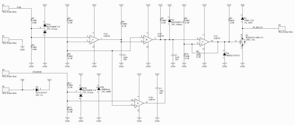
|
|
|
|
| stugray |
Jul 17 2015, 01:20 AM
Post
#15
|
|
Advanced Member Group: Members Posts: 3,825 Joined: 17-September 09 From: Longmont, CO Member No.: 10,819 Region Association: None |
First comment is make sure your design can handle +400V spikes on the input at a rate of RPM /30 (6000 RPM = 200 Hz).
It almost looks like you built a 555 Timer circuit yourself out of discrete components. I will take a closer look, but first glance looks like more components than necessary. My circuit based on this kind of megasquirt circuit after I added a 555 timer IC to the output had fewer parts. I set the timer circuit in monostable mode to stretch the short tach pulse that made it through the optocoupler for detection by a microcontroller. The exact same "pulse stretcher" could be used to hold a relay closed such that if a pulse was not detected for ~3 seconds it would open the relay. I have to look for the circuit and the notes. When I changed to a Mallory with an optical module and a MSD, I didnt need the circuit anymore as I used the output of the optical sensor. It is a nice clean 12VDC square wave. No need to protect from 400V spikes, so I tossed it in the back of a drawer somewhere. |
|
|
|
| jt914-6 |
Jul 17 2015, 04:02 PM
Post
#16
|
|
Driving & working on teeners 41 years Group: Members Posts: 1,787 Joined: 3-May 08 From: Bryant, Arkansas Member No.: 9,003 Region Association: South East States |
http://www.summitracing.com/parts/sum-890145
This is what I used on my six conversion. Easy wiring and installation. |
|
|
|
| stugray |
Jul 17 2015, 04:34 PM
Post
#17
|
|
Advanced Member Group: Members Posts: 3,825 Joined: 17-September 09 From: Longmont, CO Member No.: 10,819 Region Association: None |
QUOTE(jt914-6 @ Jul 17 2015, 04:02 PM) http://www.summitracing.com/parts/sum-890145 This is what I used on my six conversion. Easy wiring and installation. That is on my list for the race car to shut off the FP in the case of an accident. It wont stop the FP if the engine just stops though. |
|
|
|
| Spoke |
Jul 17 2015, 10:57 PM
Post
#18
|
|
Jerry Group: Members Posts: 7,185 Joined: 29-October 04 From: Allentown, PA Member No.: 3,031 Region Association: None |
Here's a circuit with a 555. Simpler than the previous circuit even including a 10V LDO to limit the voltage to the 555.
Attached thumbnail(s) 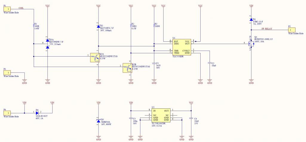
|
|
|
|
| Valy |
Jul 17 2015, 11:12 PM
Post
#19
|
|
Senior Member Group: Members Posts: 1,677 Joined: 6-April 10 From: Sunnyvale, CA Member No.: 11,573 Region Association: Northern California |
And still, my single relay circuit does the same job but its much simpler.
If you insist in using a pulse detector using 555 or discreet comppnents, add an AC component to the power supply in your spice simulations, as well as a voltage increase/drop that is RPM dependent. This will make your simulations much more interesting. Your power supply doesn't seem.robust enought. Also, do you have a parasitic capacitance in the clamping diode model? Guess what that does to your circuit, especially when you have a voltage undershot from the coil. |
|
|
|
| Mark Henry |
Jul 18 2015, 06:44 AM
Post
#20
|
|
that's what I do! Group: Members Posts: 20,065 Joined: 27-December 02 From: Port Hope, Ontario Member No.: 26 Region Association: Canada |
QUOTE(Valy @ Jul 18 2015, 01:12 AM) And still, my single relay circuit does the same job but its much simpler. (IMG:style_emoticons/default/agree.gif) I can't see why all this work? (IMG:style_emoticons/default/confused24.gif) Is it just to keep the relay on the board? (IMG:style_emoticons/default/wacko.gif) Again why? It's carbed so it's not like it's concours. (IMG:style_emoticons/default/poke.gif) The relay Valy posted works on oil pressure, the the relay I posted uses a simple tach input, both could be quickly stealth installed without a single OEM wire cut...so I don't get it? |
|
|
|
|
1 User(s) are reading this topic (1 Guests and 0 Anonymous Users)
0 Members:

|
Lo-Fi Version | Time is now: 5th July 2025 - 06:26 AM |
Invision Power Board
v9.1.4 © 2025 IPS, Inc.