|
|
|
Porsche, and the Porsche crest are registered trademarks of Dr. Ing. h.c. F. Porsche AG.
This site is not affiliated with Porsche in any way. Its only purpose is to provide an online forum for car enthusiasts. All other trademarks are property of their respective owners. |
|
|


| rpc |
 Jul 4 2017, 11:47 AM Jul 4 2017, 11:47 AM
Post
#1
|
|
Member  Group: Members Posts: 50 Joined: 18-May 11 From: Reston, VA Member No.: 13,084 Region Association: MidAtlantic Region |
Car is a 73 2.0L with stock FI. After R&R'ing the drivetrain for some much needed cleanup and hose replacement I've got a couple of questions on sensors.
1. What color is the thermo switch wire? There are two wires nearby, grey/brown and white. Just can't recall which it is. The grey/brown reaches better, but the elec. diagram shows white. 2. What is the other wire for? 3. Is the distributor air temp sensor what's called "temperature sensor I" on the electrical diagram? Thanks Attached thumbnail(s) 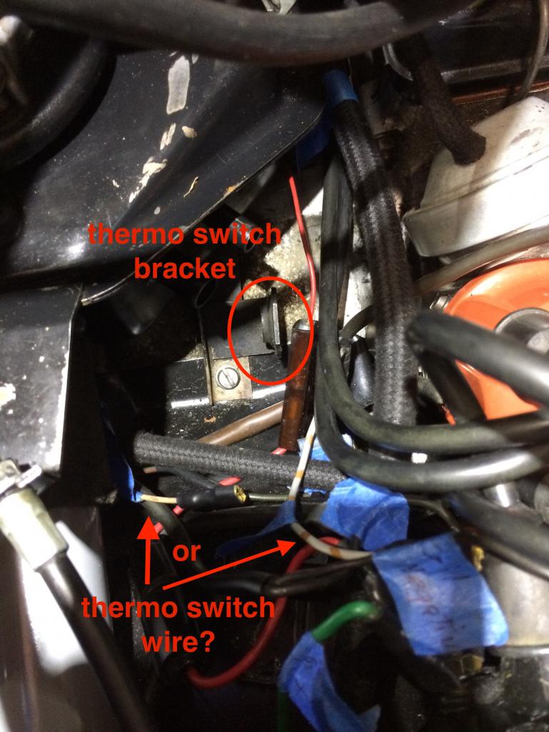
|
   |

 
|
  |
Replies(1 - 7)
| TheCabinetmaker |
Jul 4 2017, 01:06 PM
Post
#2
|
|
I drive my car everyday Group: Members Posts: 8,304 Joined: 8-May 03 From: Tulsa, Ok. Member No.: 666 |
No. Ts1 is screwed into the top of the plenum next to the tps( throttle position switch). The thermo time switch attaches to the bracket you have circled. It has a plastic plug with two wires. The single white wire plugs into the red wire next to your circle. That white wire with the orange stripes is not stock.
Btw, you car will run without those wires attached Edit. The thermal switch may only have one wire. I should be white too, but it won't have the insulated cover over the spade connector. |
|
|
|
| rpc |
Jul 4 2017, 06:12 PM
Post
#3
|
|
Member Group: Members Posts: 50 Joined: 18-May 11 From: Reston, VA Member No.: 13,084 Region Association: MidAtlantic Region |
Thanks for the response. We have the car running so know they're not absolutely necessary, but would still like to sort out these items.
Yes, the thermal switch we have only has one spade connector. Well, "had" since the spade connector broke off on ours, so we're getting another. I know it's function from PBAnders page, but couldn't recall what wire was connected to it. Sounds like the correct color is white, unless the white/orange (or grey/brown) wire in the photo is some kind of workaround. I'll have to track that down. I recall seeing the two-wire TS1. I think this is what PET calls "temperature sensor for distributor housing", part # 311-906-081-A? And, just for completeness, the CHT sensor is TS2, right? |
|
|
|
| BeatNavy |
Jul 4 2017, 06:22 PM
Post
#4
|
|
Certified Professional Scapegoat Group: Members Posts: 2,924 Joined: 26-February 14 From: Easton, MD Member No.: 17,042 Region Association: MidAtlantic Region |
QUOTE(rpc @ Jul 4 2017, 08:12 PM)  I recall seeing the two-wire TS1. I think this is what PET calls "temperature sensor for distributor housing", part # 311-906-081-A? And, just for completeness, the CHT sensor is TS2, right? Yes, TS1 has two wires. TS2 is the CHT and has one wire. |
|
|
|
| rpc |
Jul 5 2017, 07:39 AM
Post
#5
|
|
Member Group: Members Posts: 50 Joined: 18-May 11 From: Reston, VA Member No.: 13,084 Region Association: MidAtlantic Region |
Rob, thanks for confirming. The biggest challenge in sorting out these small bits has been terminology. PET, the electrical diagrams, and colloquial use seem to all differ.
|
|
|
|
| BeatNavy |
Jul 5 2017, 08:07 AM
Post
#6
|
|
Certified Professional Scapegoat Group: Members Posts: 2,924 Joined: 26-February 14 From: Easton, MD Member No.: 17,042 Region Association: MidAtlantic Region |
QUOTE(rpc @ Jul 5 2017, 09:39 AM) Rob, thanks for confirming. The biggest challenge in sorting out these small bits has been terminology. PET, the electrical diagrams, and colloquial use seem to all differ. Hi Richard - yes, it takes a while to sort it all out "in one's head." Add to that different things on different years (e.g., early/late) and I think even the experts get confused sometimes. I work in Reston and live in Sterling, and I'm happy to help in person as well if you need it. |
|
|
|
| rpc |
Jul 5 2017, 08:58 AM
Post
#7
|
|
Member Group: Members Posts: 50 Joined: 18-May 11 From: Reston, VA Member No.: 13,084 Region Association: MidAtlantic Region |
QUOTE(BeatNavy @ Jul 5 2017, 10:07 AM) QUOTE(rpc @ Jul 5 2017, 09:39 AM) Rob, thanks for confirming. The biggest challenge in sorting out these small bits has been terminology. PET, the electrical diagrams, and colloquial use seem to all differ. Hi Richard - yes, it takes a while to sort it all out "in one's head." Add to that different things on different years (e.g., early/late) and I think even the experts get confused sometimes. I work in Reston and live in Sterling, and I'm happy to help in person as well if you need it. Thanks, I'll send you a PM. |
|
|
|
| rpc |
Jul 7 2017, 02:42 PM
Post
#8
|
|
Member Group: Members Posts: 50 Joined: 18-May 11 From: Reston, VA Member No.: 13,084 Region Association: MidAtlantic Region |
Just to close off this thread.....
The grey/brown (or white/orange, if you prefer) wire in the photo was indeed a patch for the thermo switch., grafted onto the stub of the white wire. To avoid future confusion I replaced the graft with a piece of white wire. Unrelated, the red wire in the photo powers the AAR from the coil. While wrong, at least it's fused. The AAR is supposed to get power from the FP relay via pin 12 of the 12-pin connector on the Regulator Plate. Now I just need to find that white wire. Maybe it's the one in the photo? In any case, that's a different issue. |
|
|
|
|
1 User(s) are reading this topic (1 Guests and 0 Anonymous Users)
0 Members:

|
Lo-Fi Version | Time is now: 15th June 2024 - 04:51 PM |
Invision Power Board
v9.1.4 © 2024 IPS, Inc.