
 Fan Switch Help, How is this wired? Fan Switch Help, How is this wired? |
|
|

|
Porsche, and the Porsche crest are registered trademarks of Dr. Ing. h.c. F. Porsche AG.
This site is not affiliated with Porsche in any way. Its only purpose is to provide an online forum for car enthusiasts. All other trademarks are property of their respective owners. |
|
|

| Mowog4 |
 Feb 27 2018, 03:31 PM Feb 27 2018, 03:31 PM
Post
#1
|
|
Member  Group: Members Posts: 367 Joined: 2-November 15 From: Mesa AZ Member No.: 19,325 Region Association: None 
 |
I know this is an amazingly stupid question, but how does this switch get wired?
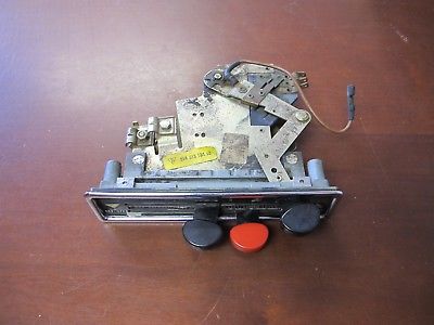 The three wires off of the switch run to the fresh air blower motor, and the brown wire is the ground. Where does the 12V+ attach to? |
   |

 
|
  |
Replies(1 - 13)
| sholman5 |
Feb 27 2018, 03:50 PM
Post
#2
|
|
Kraut burner Group: Members Posts: 197 Joined: 11-September 16 From: Ormond beach, Fl. Member No.: 20,391 Region Association: South East States
|
QUOTE(Mowog4 @ Feb 27 2018, 04:31 PM)  I know this is an amazingly stupid question, but how does this switch get wired? The three wires off of the switch run to the fresh air blower motor, and the brown wire is the ground. Where does the 12V+ attach to? There has to be one more tab to connect the red/white 12v wire to. Brown is ground. 3 wires white/green, white/yellow and white go to the 3 tabs on top. Look over the switch there has to be one more tab to connect the power to. |
|
|
|
| sholman5 |
Feb 27 2018, 04:02 PM
Post
#3
|
|
Kraut burner Group: Members Posts: 197 Joined: 11-September 16 From: Ormond beach, Fl. Member No.: 20,391 Region Association: South East States
|
Underneath where the 3 wires connect should be a single tab for pwr. Turn the unit upside.
|
|
|
|
| sholman5 |
Feb 27 2018, 04:11 PM
Post
#4
|
|
Kraut burner Group: Members Posts: 197 Joined: 11-September 16 From: Ormond beach, Fl. Member No.: 20,391 Region Association: South East States
|
QUOTE(sholman5 @ Feb 27 2018, 05:02 PM) Underneath where the 3 wires connect should be a single tab for pwr. Turn the unit upside. 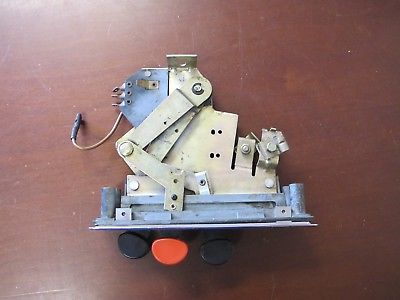 |
|
|
|
| Mowog4 |
Feb 27 2018, 04:30 PM
Post
#5
|
|
Member Group: Members Posts: 367 Joined: 2-November 15 From: Mesa AZ Member No.: 19,325 Region Association: None
|
QUOTE(sholman5 @ Feb 27 2018, 03:11 PM) QUOTE(sholman5 @ Feb 27 2018, 05:02 PM) Underneath where the 3 wires connect should be a single tab for pwr. Turn the unit upside. Thanks, makes my life much easier |
|
|
|
| JFG |
Feb 28 2018, 02:34 PM
Post
#6
|
|
Senior Member Group: Members Posts: 686 Joined: 7-April 16 From: Wales Member No.: 19,869 Region Association: None |
So the single tab underneath, fixed to the plate a short space from the line of 3 connectors is for a live power wire?
If so what colour combo is this power wire? QUOTE(sholman5 @ Feb 27 2018, 10:11 PM) QUOTE(sholman5 @ Feb 27 2018, 05:02 PM) Underneath where the 3 wires connect should be a single tab for pwr. Turn the unit upside. |
|
|
|
| Mowog4 |
Mar 1 2018, 10:47 PM
Post
#7
|
|
Member Group: Members Posts: 367 Joined: 2-November 15 From: Mesa AZ Member No.: 19,325 Region Association: None
|
My wire on the top (brown) and the tab underneath are connected if I put a continuity tester on it. What am I missing?
QUOTE(sholman5 @ Feb 27 2018, 03:02 PM) Underneath where the 3 wires connect should be a single tab for pwr. Turn the unit upside. |
|
|
|
| JFG |
Mar 2 2018, 01:27 AM
Post
#8
|
|
Senior Member Group: Members Posts: 686 Joined: 7-April 16 From: Wales Member No.: 19,869 Region Association: None |
I started a thread on the wiring of this switch a while ago but never got an accurate answer. From memory the tab on top and underneath appear to both be earths. 1 came from the hot air switch by the gearstick but no-one confirmed the other wire.
|
|
|
|
| Tbrown4x4 |
Mar 2 2018, 03:54 AM
Post
#9
|
|
Senior Member Group: Members Posts: 708 Joined: 13-May 14 From: Port Orchard, WA Member No.: 17,338 Region Association: None
|
(IMG:style_emoticons/default/dry.gif)
I did what I could without cutting up my wire harness. Did wiring diagrams go out of print? (IMG:style_emoticons/default/confused24.gif) Check Jeff Bowlsby's website. |
|
|
|
| Tbrown4x4 |
Mar 2 2018, 04:01 AM
Post
#10
|
|
Senior Member Group: Members Posts: 708 Joined: 13-May 14 From: Port Orchard, WA Member No.: 17,338 Region Association: None
|
PS. The 12V supply goes to the fan motor.
|
|
|
|
| BeatNavy |
Mar 2 2018, 05:42 AM
Post
#11
|
|
Certified Professional Scapegoat Group: Members Posts: 2,967 Joined: 26-February 14 From: Easton, MD Member No.: 17,042 Region Association: MidAtlantic Region
|
Not 100% sure what the question is at this point, but:
All the brown wires to that assembly are grounds. IIRC, the only hot lead going to (or near) that assembly is for the light to let you know you're on one of the blower speeds (I, II, or III) and not just opening the baffles in the blower housing. So basically: 1. Top lever all the way to the left means baffles should be closed preventing air from coming through the vent from high air pressure area above grill while car is moving. 2. As you move lever to the right, baffles open allowing some air from that high pressure area through the vents. 3. You move the lever further to the right and it grounds the first (I) wire which does two things: grounds the light in the dash at the assembly (so it lights up!) and provides a ground path for the blower motor upfront. So now you're also pulling air through the vent with the fan. Settings II and III increase fan speed. I believe 12v is supplied directly to the fan motor (as Tbrown said), but that circuit is not grounded until you move that lever to one of the 3 settings and provide it a ground. There is a resistor pack in the fan housing. The I fan setting routes ground through the most resistance. The III setting routes it through the least, so the motor gets more power. Convoluted answer, but that's my recollection. Someone correct me if I bollocksed that up. Here's a picture of the resistor pack in the fan housing. 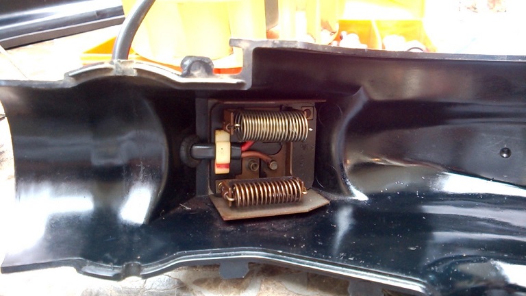 and here's what that looks like from the outside of the housing. You can see where the 4-prong connector attaches. So the wires at the switch assembly should have continuity to one of these prongs through the connector. 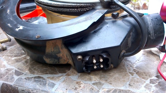 |
|
|
|
| theer |
Mar 2 2018, 07:58 AM
Post
#12
|
|
Senior Member Group: Members Posts: 692 Joined: 31-July 15 From: Dover, MA Member No.: 19,014 Region Association: North East States
|
(IMG:style_emoticons/default/agree.gif)
This is basically the on/off switch for the blower, with the ground being the switch leg. Power goes to the fan, the ground from the fan goes to this switch.. the switch completes ground to let power flow. |
|
|
|
| Mowog4 |
Mar 2 2018, 10:38 AM
Post
#13
|
|
Member Group: Members Posts: 367 Joined: 2-November 15 From: Mesa AZ Member No.: 19,325 Region Association: None
|
QUOTE(theer @ Mar 2 2018, 06:58 AM) (IMG:style_emoticons/default/agree.gif) This is basically the on/off switch for the blower, with the ground being the switch leg. Power goes to the fan, the ground from the fan goes to this switch.. the switch completes ground to let power flow. Perfect explanation, thanks. I am going to use the switch to run an AC/Heat unit and wanted to understand the circuit. |
|
|
|
| theer |
Mar 2 2018, 01:41 PM
Post
#14
|
|
Senior Member Group: Members Posts: 692 Joined: 31-July 15 From: Dover, MA Member No.: 19,014 Region Association: North East States
|
(IMG:style_emoticons/default/beerchug.gif)
I had the exact same thought for my Suby project, but am nowhere near the point of figuring out electrical connections. My thought was to use the stock HVAC system as much as possible... like I said.. not there yet. Keep us posted with your solution - lots of water-cooled conversions out there. Where are you putting the heater core/AC evaporator? Remember, you have a another similar switch on the tunnel controlling the aux heater fan in the engine compartment that could be used. The 944 (and 911, etc.) electronic heater control units from the 80's-90's is something I was thinking might also work (heat, A/C, fans, temp setting) all in one.. would just need to motorize the HVAC valves currently controlled by wires. Good luck. |
|
|
|
|
1 User(s) are reading this topic (1 Guests and 0 Anonymous Users)
0 Members:

|
Lo-Fi Version | Time is now: 22nd August 2026 - 03:24 PM |
Invision Power Board
v9.1.4 © 2026 IPS, Inc.