|
|
|
Porsche, and the Porsche crest are registered trademarks of Dr. Ing. h.c. F. Porsche AG.
This site is not affiliated with Porsche in any way. Its only purpose is to provide an online forum for car enthusiasts. All other trademarks are property of their respective owners. |
|
|


| doug_b_928 |
 Mar 2 2018, 08:49 PM Mar 2 2018, 08:49 PM
Post
#1
|
|
Senior Member  Group: Members Posts: 692 Joined: 17-January 13 From: Winnipeg Member No.: 15,382 Region Association: Canada |
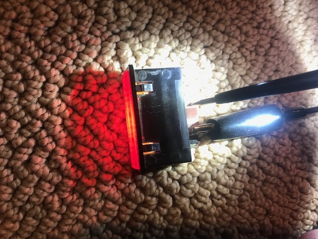
I'm trying to determine if my safety belt warning light is good. It's from a 73. The car is completely disassembled, including the wiring harness. There are 4 wires that go to the light. On the back of the light are 4 contact points, one for each wire. When I put power and ground in various combinations to the 4 points, I can only get the light to illuminate when the ground is on the left-most contact point (where the yellow wire goes) and put power to the second contact point from the right (where the black wire goes). Does this sound like the correct operation for this light, or should other power and ground combinations also cause it to illuminate? If no one knows for sure, if anyone has one they could test I'd appreciate it. Here's a pic of the only combination that will illuminate the light.
 |
   |

 
|
  |
Replies(1 - 11)
| JeffBowlsby |
Mar 2 2018, 09:18 PM
Post
#2
|
|
914 Wiring Harnesses Group: Members Posts: 8,524 Joined: 7-January 03 From: San Ramon CA Member No.: 104 Region Association: None |
You come up with interesting questions Doug. (IMG:style_emoticons/default/first.gif)
The seatbelt light you refer to (4 pole) is only on the 72-73 cars. 70-71 did not have them. 74-76 had a 2 pole version, but it functions differently than your 73 version. The 'light' is more than a light, it is a circuit with an IC and diodes and more... Item 67 on the schematic is the 4 pole light. You can trace the yellow wire to be switched grounds triggered by the passenger seat sensor and the door sensors. I have not studied the rest of the schematic to understand how to all works. Attached image(s) 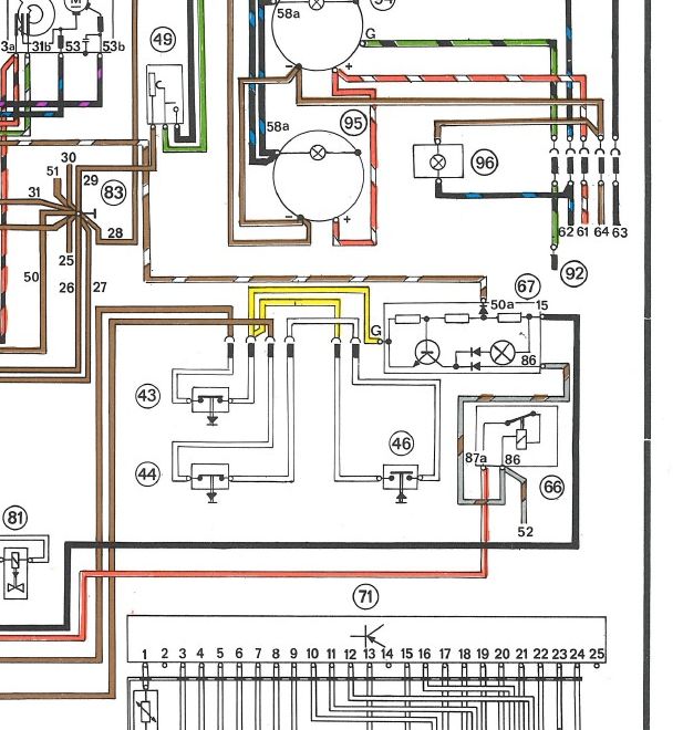
|
 |
|
| doug_b_928 |
Mar 2 2018, 09:28 PM
Post
#3
|
|
Senior Member Group: Members Posts: 692 Joined: 17-January 13 From: Winnipeg Member No.: 15,382 Region Association: Canada |
Thanks, Jeff. There will be more questions to come (IMG:style_emoticons/default/smile.gif). That brown/white wire is one of the ones coming from that diode that I was asking about in the wire resto thread. It’s all way over my head, which is why I was hoping someone would have a known good one they could put power and ground to in the various combinations so that we could see if it operates the same as mine.
|
|
|
|
| doug_b_928 |
May 14 2018, 05:04 AM
Post
#4
|
|
Senior Member Group: Members Posts: 692 Joined: 17-January 13 From: Winnipeg Member No.: 15,382 Region Association: Canada |
Bumping this thread to see if anyone has a known good one that they can put power and ground to the 4 poles in various combinations to see if it operates the same as mine.
|
|
|
|
| bbrock |
May 14 2018, 08:04 AM
Post
#5
|
|
914 Guru Group: Members Posts: 5,269 Joined: 17-February 17 From: Montana Member No.: 20,845 Region Association: Rocky Mountains |
I never paid attention before, but this is a fun little circuit for a sometimes electronics hobbyist like me. Bear in mind I'm only a hobbyist, but I'm pretty sure I have this one figured out.
To test, you would connect G to ground and connect a test light or buzzer in series to 86 with power applied to the test light.. At this point, the belt light or test light should NOT light up. Next, apply power to 15 and both lights should turn on. Then, connect 50a to ground and they should both go out. [EDIT: Connecting power to only 15 and G to ground should light the seat belt indicator but not the test light, even if you connect the test light to ground (because of the diode). Here's what's happening. The circuit is a transistor switch. When the ignition switch is turned on, the base of of the transistor is energized which closes the "switch" in the transistor to allow power to flow through the buzzer, and the belt light to ground so the light turns on. However, the brown/white wire is connected to the hand brake switch. If the hand brake is pulled, that wire is connected to ground which bleeds off voltage from the base of the transistor. Presumably, this reduces voltage to the base below the threshold needed to keep the transistor "switch" closed, so when the hand brake is pulled, no current flows through the belt light or test light and they g off. I say presumably, because we need to know the resistor values to know how much voltage is going to the transistor base when the hand brake is pulled, but it looks like that part of the circuit acts as a voltage divider when the brake lever is pulled. Finally, the ground circuit runs through 3 mechanical switches so that the ground is completed only when the driver's seat belt is not buckled; OR someone is sitting in the passenger seat AND the passenger belt is not buckled. The upshot is that 3 conditions must be met for the seat belt light to come on (and the buzzer to buzz): 1. ignition switch on 2. hand brake off 3. at least on seat belt on an occupied seat unbuckled Hope that helps (IMG:style_emoticons/default/beer.gif) |
|
|
|
| 914_teener |
May 14 2018, 08:21 AM
Post
#6
|
|
914 Guru Group: Members Posts: 5,204 Joined: 31-August 08 From: So. Cal Member No.: 9,489 Region Association: Southern California |
Having troubles with this circuit with above is all correct...also the door swithes also are switched grounds through the buzzer which will function as a "Door Ajar" if open, meaning the doors and switches.
You will discover this if the door switches are worn out. BTDT. |
|
|
|
| 914_teener |
May 14 2018, 08:30 AM
Post
#7
|
|
914 Guru Group: Members Posts: 5,204 Joined: 31-August 08 From: So. Cal Member No.: 9,489 Region Association: Southern California |
Btw.....my car works as it should...if you want me to test it PM me.
I chased a problem with this circuit for months. |
|
|
|
| doug_b_928 |
May 14 2018, 08:58 AM
Post
#8
|
|
Senior Member Group: Members Posts: 692 Joined: 17-January 13 From: Winnipeg Member No.: 15,382 Region Association: Canada |
Thanks very much guys! So in my earlier test where I could only get the light to light when I had the ground on G and the power on 15, that is as it should be. Based on Brent's logic, I should also apply power to 86 and 15 at the same time and it should still light. Then bridge 50 to ground and it should go out. I'll give that a try and report back.
|
|
|
|
| bbrock |
May 14 2018, 10:03 AM
Post
#9
|
|
914 Guru Group: Members Posts: 5,269 Joined: 17-February 17 From: Montana Member No.: 20,845 Region Association: Rocky Mountains |
QUOTE(doug_b_928 @ May 14 2018, 08:58 AM)  Thanks very much guys! So in my earlier test where I could only get the light to light when I had the ground on G and the power on 15, that is as it should be. Based on Brent's logic, I should also apply power to 86 and 15 at the same time and it should still light. Then bridge 50 to ground and it should go out. I'll give that a try and report back. Yes, and my first description is a little wrong. In my first read of the circuit, I didn't notice that the indicator light was taking power from 15 rather than rather than 86 and didn't revise everything I should have after noticing that. So to revise, V+ on 15 and G to ground would cause the indicator to light. If you attach a powered test light in series to 86, it should light ONLY when you also have power to 15, and removing power from 15 should cause both lights to go out. The circuit is very similar to the 3rd diagram on this page: https://learn.sparkfun.com/tutorials/transi...ions-i-switches |
|
|
|
| doug_b_928 |
May 14 2018, 10:28 AM
Post
#10
|
|
Senior Member Group: Members Posts: 692 Joined: 17-January 13 From: Winnipeg Member No.: 15,382 Region Association: Canada |
Excellent, thanks. When I apply power to 15 (the one I had it on in my first post) the light of course comes on. If I also add power to 86 the light stays on. Power to 86 alone does not cause the light to turn on. If I have the power on and bridge 50 and G the light goes out (regardless of whether I have power to 86). Does that sound right?
|
|
|
|
| bbrock |
May 14 2018, 10:47 AM
Post
#11
|
|
914 Guru Group: Members Posts: 5,269 Joined: 17-February 17 From: Montana Member No.: 20,845 Region Association: Rocky Mountains |
QUOTE(doug_b_928 @ May 14 2018, 10:28 AM) Excellent, thanks. When I apply power to 15 (the one I had it on in my first post) the light of course comes on. If I also add power to 86 the light stays on. Power to 86 alone does not cause the light to turn on. If I have the power on and bridge 50 and G the light goes out (regardless of whether I have power to 86). Does that sound right? Sounds good. The last test would be to see if removing power from 15 breaks the circuit between 86 and ground. But you have already shown that the transistor is working correctly. Did you have power on 15 when you bridged 50 to G? |
|
|
|
| doug_b_928 |
May 14 2018, 11:33 AM
Post
#12
|
|
Senior Member Group: Members Posts: 692 Joined: 17-January 13 From: Winnipeg Member No.: 15,382 Region Association: Canada |
Yes, powerbon 15 (light on), then making the bridge turned the light off. Thanks so much!!
|
|
|
|
|
1 User(s) are reading this topic (1 Guests and 0 Anonymous Users)
0 Members:

|
Lo-Fi Version | Time is now: 2nd June 2024 - 01:55 AM |
Invision Power Board
v9.1.4 © 2024 IPS, Inc.