|
|
|
Porsche, and the Porsche crest are registered trademarks of Dr. Ing. h.c. F. Porsche AG.
This site is not affiliated with Porsche in any way. Its only purpose is to provide an online forum for car enthusiasts. All other trademarks are property of their respective owners. |
|
|


| Literati914 |
 Aug 13 2024, 06:31 PM Aug 13 2024, 06:31 PM
Post
#1
|
|
Advanced Member  Group: Members Posts: 2,165 Joined: 16-November 06 From: Dallas, TX Member No.: 7,222 Region Association: Southwest Region |
I have a set of 4 into 1 stainless headers that I want to connect up with an old stainless steel 1in-2out Tangerine muffler. The muffler was obviously not made for this header system but they are not that far off either. Well a little is a lot in this case I guess.
I have a MIG welder and thought I’d buy some self-shielded stainless wire (rather than invest in a whole tank of gas), and try to fix the gap. If nothing else I figured I could tack up a solution and let a real welder finish it (if blowing holes became unavoidable). I’ve found that the tube exiting the muffler is apparently made up of mild steel at the flange (magnet sticks strongly), then the curved mid-section of the tube is a low carbon steel (magnet sticks BUT NOT strongly), then the very short part is all stainless as is the rest of the muffler (magnet does not stick). I’m looking for suggestions as to where you guys would cut, maybe good only spots to buy pre-curved stainless or what to search for. General suggestions would be appreciated. Part of wanting to take on this task is that I’d like to add to my welding experience if I can. Here are some pics of the project: Attached image(s) 
|
   |

 
|
  |
Replies(1 - 19)
| Literati914 |
Aug 13 2024, 06:32 PM
Post
#2
|
|
Advanced Member Group: Members Posts: 2,165 Joined: 16-November 06 From: Dallas, TX Member No.: 7,222 Region Association: Southwest Region |
Another view
Attached image(s) 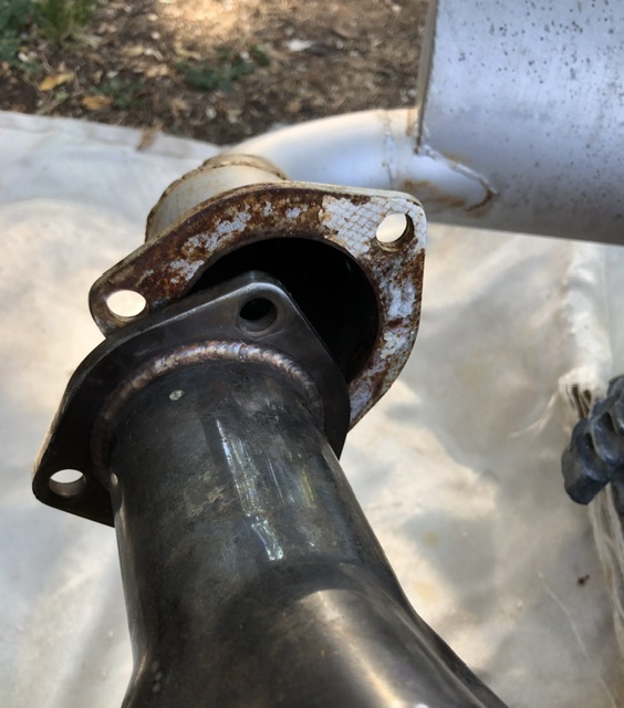
|
|
|
|
| Literati914 |
Aug 13 2024, 06:33 PM
Post
#3
|
|
Advanced Member Group: Members Posts: 2,165 Joined: 16-November 06 From: Dallas, TX Member No.: 7,222 Region Association: Southwest Region |
Another view again
Attached image(s) 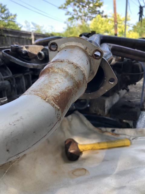
|
|
|
|
| Literati914 |
Aug 13 2024, 06:37 PM
Post
#4
|
|
Advanced Member Group: Members Posts: 2,165 Joined: 16-November 06 From: Dallas, TX Member No.: 7,222 Region Association: Southwest Region |
At the header, I’ve actually slid the collector down about 1/2” in these pics so that the flanges would touch. I think there is still plenty primary pipe inside the collector, but is there a minimum I should be concerned with? I could obviously move it back where it was designed to sit, if changing the muffler input area anyway.
Attached image(s) 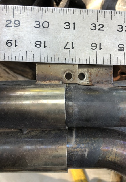
|
|
|
|
| mb911 |
Aug 14 2024, 03:54 AM
Post
#5
|
|
914 Guru Group: Members Posts: 7,694 Joined: 2-January 09 From: Burlington wi Member No.: 9,892 Region Association: Upper MidWest |
Ok there is no way that muffler is stainless as it is rusting in a way stainless doesn’t. Are wanting to modify the header or the muffler? Always cut the straight section never in a bend
|
|
|
|
| ChrisFoley |
Aug 14 2024, 04:57 AM
Post
#6
|
|
I am Tangerine Racing Group: Members Posts: 8,016 Joined: 29-January 03 From: Bolton, CT Member No.: 209 Region Association: None |
I think the muffler inlet was altered by someone else already. Everything but the flange and first few inches is stainless. (I could be wrong. It was made a long time ago.)
It appears that two cuts and two short pieces of tubing would get you where you're trying to go. |
|
|
|
| mb911 |
Aug 14 2024, 07:08 AM
Post
#7
|
|
914 Guru Group: Members Posts: 7,694 Joined: 2-January 09 From: Burlington wi Member No.: 9,892 Region Association: Upper MidWest |
QUOTE(ChrisFoley @ Aug 14 2024, 02:57 AM)  I think the muffler inlet was altered by someone else already. Everything but the flange and first few inches is stainless. (I could be wrong. It was made a long time ago.) It appears that two cuts and two short pieces of tubing would get you where you're trying to go. (IMG:style_emoticons/default/agree.gif) |
|
|
|
| infraredcalvin |
Aug 14 2024, 08:11 AM
Post
#8
|
|
Distracted Member Group: Members Posts: 1,701 Joined: 25-August 08 From: Ladera Ranch, CA Member No.: 9,463 Region Association: Southern California |
(IMG:style_emoticons/default/agree.gif) cut in 2 places where shown, you have to extend it out away from the muffler, then you need to rotate the flange, so you might as well extend the flange so the collectors are fit in the correct position.
 |
|
|
|
| Literati914 |
Aug 14 2024, 10:43 AM
Post
#9
|
|
Advanced Member Group: Members Posts: 2,165 Joined: 16-November 06 From: Dallas, TX Member No.: 7,222 Region Association: Southwest Region |
Right, your suggestions are along the lines of what I’ve been thinking.. only thing though is that I’m gonna need a “small drop down” section (probably just off the muffler) - like a soft “Z” shape, to get to the lower placement of the header flange. Is anything like that even available- or would it need to be made ?
|
|
|
|
| infraredcalvin |
Aug 14 2024, 11:31 AM
Post
#10
|
|
Distracted Member Group: Members Posts: 1,701 Joined: 25-August 08 From: Ladera Ranch, CA Member No.: 9,463 Region Association: Southern California |
Googling, apparently it’s called an ‘s‘ bend. They look to be much longer than what it appears you need.
Let’s call the cut next to the muffler cut 1 and the one near the flange cut 2. Seems you could rotate cut 1 to account for the drop, then the extension piece you need to add at cut 2 could be slightly to account for any alignment. This would essentially create the “z’ you mention. |
|
|
|
| TonyVan |
Aug 14 2024, 04:26 PM
Post
#11
|
|
Newbie Group: Members Posts: 39 Joined: 3-December 07 From: San Jose, Ca Member No.: 8,412 Region Association: Northern California |
Is it possible to bolt the muffler to the header and use a torch to heat the muffler part to bend it the way you need? Just a thought. Cant weld so no real experience.
Tony QUOTE(infraredcalvin @ Aug 14 2024, 10:31 AM) Googling, apparently it’s called an ‘s‘ bend. They look to be much longer than what it appears you need. Let’s call the cut next to the muffler cut 1 and the one near the flange cut 2. Seems you could rotate cut 1 to account for the drop, then the extension piece you need to add at cut 2 could be slightly to account for any alignment. This would essentially create the “z’ you mention. |
|
|
|
| Literati914 |
Aug 14 2024, 04:46 PM
Post
#12
|
|
Advanced Member Group: Members Posts: 2,165 Joined: 16-November 06 From: Dallas, TX Member No.: 7,222 Region Association: Southwest Region |
QUOTE(TonyVan @ Aug 14 2024, 05:26 PM) Is it possible to bolt the muffler to the header and use a torch to heat the muffler part to bend it the way you need? Just a thought. Cant weld so no real experience. Tony assuming the muffler body is released from it's mounting point... and the flanges are then bolted together - the muffler would then be pointing upwards at about a 45degree angle. Getting the curved pipe red hot and pushing the muffler downwards to meet it's original mounting locations would probably just twist/collapse the curved pipe in on itself, no? Also, that would likely take more heat than I could build up too (only got a small bottle MAP torch, besides the Mig welder) I think I'm gonna buy a "U" shape pieces and cut several pieces from it, possibly to include small "pie" cuts for a gradual step down if needed. |
|
|
|
| Literati914 |
Aug 14 2024, 07:47 PM
Post
#13
|
|
Advanced Member Group: Members Posts: 2,165 Joined: 16-November 06 From: Dallas, TX Member No.: 7,222 Region Association: Southwest Region |
Ok well I made the cut at the muffler end of the curved pipe.. and bolted the flanges together
Attached image(s) 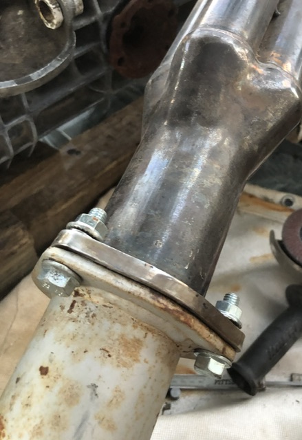
|
|
|
|
| Literati914 |
Aug 14 2024, 07:48 PM
Post
#14
|
|
Advanced Member Group: Members Posts: 2,165 Joined: 16-November 06 From: Dallas, TX Member No.: 7,222 Region Association: Southwest Region |
Also drove the collector up to where it’s supposed to sit:
Attached image(s) 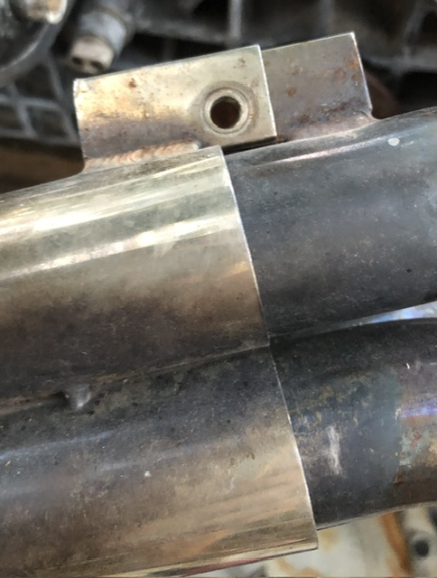
|
|
|
|
| Literati914 |
Aug 14 2024, 07:51 PM
Post
#15
|
|
Advanced Member Group: Members Posts: 2,165 Joined: 16-November 06 From: Dallas, TX Member No.: 7,222 Region Association: Southwest Region |
Now I can see the situation better..
if I now make a cut at the muffler’s flange and clock the curved pipe downward just a little bit, the pieces will line up nicely. No need for a “Z/S” shape: Attached image(s) 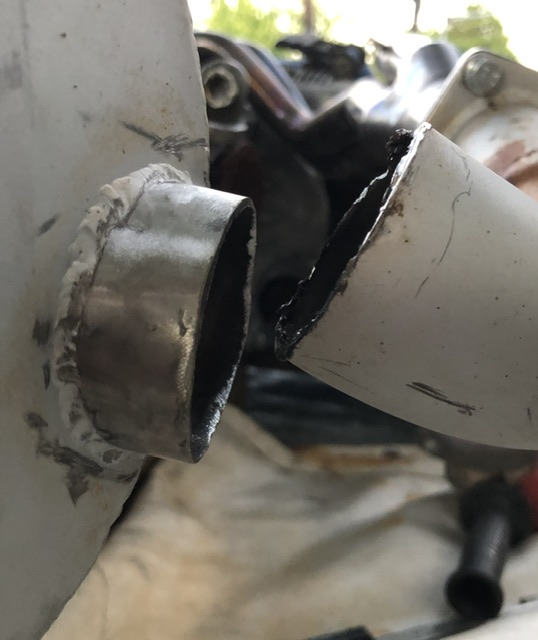
|
|
|
|
| Literati914 |
Aug 14 2024, 07:52 PM
Post
#16
|
|
Advanced Member Group: Members Posts: 2,165 Joined: 16-November 06 From: Dallas, TX Member No.: 7,222 Region Association: Southwest Region |
Looks like only a 1/2”- 3/4” filler piece of stainless will be needed to bridge the gap:
Attached image(s) 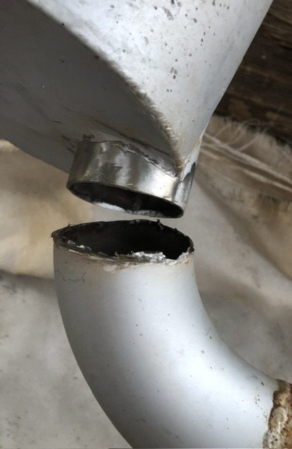
|
|
|
|
| ChrisFoley |
Aug 15 2024, 07:31 AM
Post
#17
|
|
I am Tangerine Racing Group: Members Posts: 8,016 Joined: 29-January 03 From: Bolton, CT Member No.: 209 Region Association: None |
I would still make the second cut where infraredcalvin drew it. That will give you more flexibility to make adjustments when you try to align it all together, and it will be easier to weld than right at the flange.
|
|
|
|
| Shivers |
Aug 15 2024, 07:53 AM
Post
#18
|
|
Senior Member Group: Members Posts: 3,203 Joined: 19-October 20 From: La Quinta, CA Member No.: 24,781 Region Association: Southern California |
Sorry but I have to ask, are you not defeating the reason for a header in the first place but choking it off at the muffler inlet pipe? Maybe you could knock a piece of wood into the inlet pipe and run a hole saw to get a bigger hole in the muffler and then weld in a pipe that is closer to the diameter of the header outlet? Just curious about the reduction
@Literati914 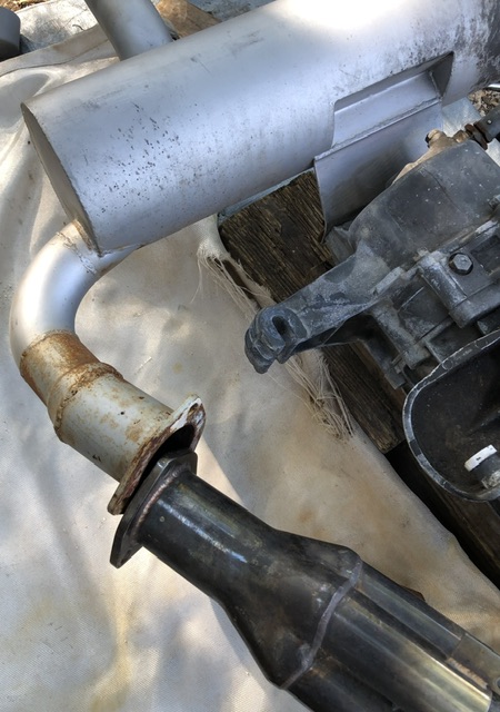 |
|
|
|
| Flyinlow |
Aug 15 2024, 08:12 AM
Post
#19
|
|
Flyinlow Group: Members Posts: 99 Joined: 17-October 20 From: British Columbia, Canada Member No.: 24,774 Region Association: Canada |
QUOTE(Shivers @ Aug 15 2024, 06:53 AM) Sorry but I have to ask, are you not defeating the reason for a header in the first place but choking it off at the muffler inlet pipe? Maybe you could knock a piece of wood into the inlet pipe and run a hole saw to get a bigger hole in the muffler and then weld in a pipe that is closer to the diameter of the header outlet? Just curious about the reduction @Literati914 I agree that the reduction might be too much |
|
|
|
| ChrisFoley |
Aug 15 2024, 12:38 PM
Post
#20
|
|
I am Tangerine Racing Group: Members Posts: 8,016 Joined: 29-January 03 From: Bolton, CT Member No.: 209 Region Association: None |
Actually, the inexpensive collector is far from optimized. The pipe going into the flange is way too big. Other than trying to make the reducer smoother, I don't think there's much to be gained by enlarging the muffler inlet.
|
|
|
|
|
1 User(s) are reading this topic (1 Guests and 0 Anonymous Users)
0 Members:

|
Lo-Fi Version | Time is now: 7th December 2025 - 07:03 AM |
Invision Power Board
v9.1.4 © 2025 IPS, Inc.