|
|
|
Porsche, and the Porsche crest are registered trademarks of Dr. Ing. h.c. F. Porsche AG.
This site is not affiliated with Porsche in any way. Its only purpose is to provide an online forum for car enthusiasts. All other trademarks are property of their respective owners. |
|
|


| type47 |
 Nov 21 2007, 04:06 PM Nov 21 2007, 04:06 PM
Post
#1
|
|
Viermeister  Group: Members Posts: 4,254 Joined: 7-August 03 From: Vienna, VA Member No.: 994 Region Association: MidAtlantic Region |
got a chance to do some work on the teener today. plans were to weld (IMG:style_emoticons/default/welder.gif) in a bung for an O2 sensor for LM-1. rod (root) was going to do some tig work on the bung. problems with car on the way to his shop. car quit twice. i carry a pressure gauge so i connected it on the cold start valve port and got zero pressure. simple i thought, bad fuel pump. even connected a voltmeter to the fuel pump power plug to verify voltage to the pump. however, didn't see that voltage was 12 mV not 12 V (where are my glasses...). long story short, i was able to get to rods shop and, third times a charm, bung got welded in (by the way, this may be a "DUH" to many but don't try to weld in the bung with the plug screwed into the bung, it'll just seize the plug. i/we didn't know any better). attempt to start the car to go home, no start. no pressure then we observe 12milliVolts at the pump connector. rod says all signs are pointing to a bad relay board and graciously lends me his relay board to get me home (IMG:style_emoticons/default/smilie_pokal.gif) so now my question is: how often/frequent do these fail and would like to hear some experiences about how the faulty board was discovered. it's hard for me to believe the board failed and i'm going to do some continuity tests on it. to me, all signs led to a bad fuel pump.
|
   |

 
|
  |
Replies(1 - 5)
| brp986s |
Nov 21 2007, 04:31 PM
Post
#2
|
|
Member Group: Members Posts: 434 Joined: 27-September 07 From: los angeles Member No.: 8,167 |
I've heard of the boards going bad due to corrosion of the riveted electrical connections on the underside. But first I would pop out the pump fuse and clean the contacts, as well as swapping in a pump relay.
|
|
|
|
| bperry |
Nov 21 2007, 04:48 PM
Post
#3
|
|
Lurker Group: Members Posts: 477 Joined: 16-February 04 From: Dallas, Tx Member No.: 1,661 |
The relay board is braindead simple that is why it seldom fails.
It is just thick copper traces attached by rivets to connectors. But I had one that did and it wasn't a hard/permanent failure. It would work and fail intermittently. It turned out to be a simple problem but not obvious at all. It was a trace that had cracked and worked its way loose from a rivet that is attached to the fuse holder. 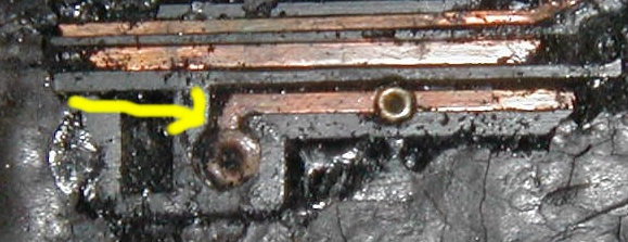 --- bill Below is some information from a previous post I did about this. ----------------------------------------------------------------------- As far as actually testing the actual relay board, the method that I've used is to "yellow line" the board. Start by making a zerox copy of the relay board wiring diagram from something like the Haynes manual page 147 or 161. Then get a ohm meter that beeps when continuity is zero. I have a small digital unit from radio shack that has a continuity setting. Then "ohm out" each wire connection one at a time and as you test the continuity between each point. As each trace check out, use a yellow highlighter to mark each trace on your zerox copy. NOTE: this will only find "hard" failures and will not find intermittent failures which can be quite common where the rivets attach connectors to the traces. If you want to visually inspect all the copper traces you will have to remove all the factory tar from the board. I found that this can be done fairly easily with a dental pick and a small screwdriver. It helps if the tar is cold, so if its not cold from your garage, put it in the freezer for a while to chill the tar which makes it alot easier to chip away from the board. Once most of the tar is removed you can visually inspect the traces. To solder the rivets to the traces to make things really secure, you'll have to clean the traces/rivets really well. For a quick check, you may want to check the rivets/traces directly under the fuse holders or those that were exposed to the air from chipped away tar first. Those seem to fail first because the heat from the fuses heats up the tar which causes it to fall off and exposes the rivets to the air which then causes them to oxidize and stop carrying full current load to things like the fuel pump. Good luck. |
|
|
|
| type47 |
Nov 21 2007, 05:16 PM
Post
#4
|
|
Viermeister Group: Members Posts: 4,254 Joined: 7-August 03 From: Vienna, VA Member No.: 994 Region Association: MidAtlantic Region |
i did the swapping of the fuel pump relay for a good relay (headlight motor relay).i just traced all the terminals for continuity and could not find a fault. i took a pic of the board connections and just went every connection pin to where ever it went and tested for continuity and found everything checking out OK. there is some corrosion so i'm going to clean the board and clean all the connections and reinstall the board and start looking for another board as backup. who would have thought to carry a backup relay board along with all the other tools a teener has to pack! (IMG:style_emoticons/default/smash.gif)
|
|
|
|
| Tom |
Nov 21 2007, 06:49 PM
Post
#5
|
|
Advanced Member Group: Members Posts: 2,139 Joined: 21-August 05 From: Port Orchard, WA 98367 Member No.: 4,626 Region Association: None |
An ohmmeter is a good troubleshooting tool, but it has it's limitations. A circuit that reads good with the ohmmeter may in fact break down when asked to carry current. A better way is to put the load on the connection and then read voltage at the load. If your voltage is low, the the circiut is breaking down some where. Clean all of the connections and where possible solder the rivets on the relay board. Some time back , when I had the engine out , I pulled the relay board and checked it with an ohmmeter and while the meter was hooked up , wiggled and pushed on fuse clips and connectors. Found several suspect one and cleaned and soldered them. Since then "0" problems with the relay board.
Tom |
|
|
|
| JeffBowlsby |
Nov 21 2007, 08:31 PM
Post
#6
|
|
914 Wiring Harnesses & Beekeeper Group: Members Posts: 9,319 Joined: 7-January 03 From: San Ramon CA Member No.: 104 Region Association: None |
QUOTE(brp986s @ Nov 21 2007, 02:31 PM)  But first I would pop out the pump fuse and clean the contacts, as well as swapping in a pump relay. There is no dedicated fuel pump fuse, only the 25A main fuse which is located at the aft fuseholder on the 914/4 regulator plate. Another thing to check is the AAR circuit, it is shared with the fuel pump. If the AAR wiring shorts out (especially check where the wire enters the AAR housing) , it can take the fuel pump circuit down too. |
|
|
|
|
2 User(s) are reading this topic (2 Guests and 0 Anonymous Users)
0 Members:

|
Lo-Fi Version | Time is now: 2nd August 2026 - 01:02 AM |
Invision Power Board
v9.1.4 © 2026 IPS, Inc.