|
|
|
Porsche, and the Porsche crest are registered trademarks of Dr. Ing. h.c. F. Porsche AG.
This site is not affiliated with Porsche in any way. Its only purpose is to provide an online forum for car enthusiasts. All other trademarks are property of their respective owners. |
|
|


| Cevan |
 May 11 2009, 11:47 AM May 11 2009, 11:47 AM
Post
#1
|
|
Senior Member  Group: Members Posts: 1,079 Joined: 11-December 06 From: Western Massachusetts Member No.: 7,351 |
I've completed my 1.8 to 2.0 motor swap and have my car running really good, except the TPS is worn right around the partially open throttle position.
I've cleaned the surface and the contacts with 2000 grit sandpaper and then used Deoxit electrial contact cleaner. This helped as it only hesitates/bucks at the barely open throttle position and cleared up the issue at positions further along the path of travel. I imagine that it's worn right at the spot where you're most often running at. I searched but couldn't find any threads on repairing this. What I want to do is move the circuit board to the right or left, so that the contacts run on a fresh part of the board. Any ideas on how to separate the circuit board from the metal body and how best to reattach it? It looks like it may be soldered at the bottom right corner. 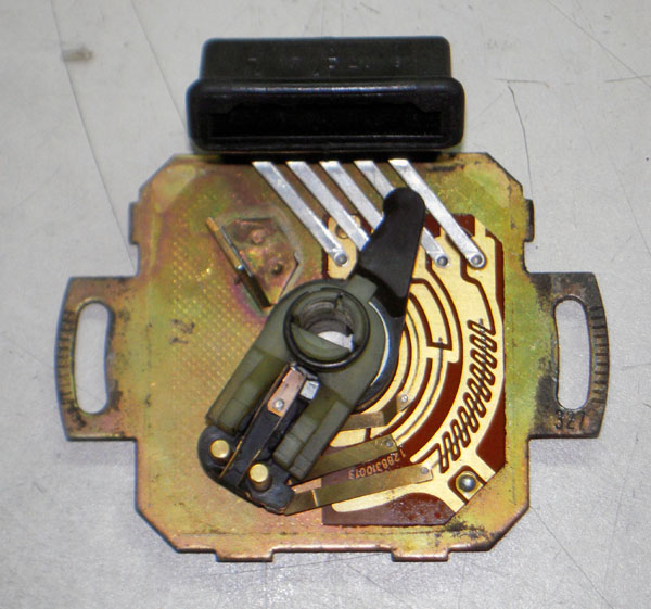 |
   |

 
|
  |
Replies(1 - 19)
| McMark |
May 11 2009, 11:50 AM
Post
#2
|
|
914 Freak! Group: Retired Admin Posts: 20,180 Joined: 13-March 03 From: Grand Rapids, MI Member No.: 419 Region Association: None |
Using careful pressure, you can slightly bend the 'fingers' to run on a new area of the circuit board. No need to make it more complicated than that.
|
|
|
|
| Cevan |
May 12 2009, 05:39 AM
Post
#3
|
|
Senior Member Group: Members Posts: 1,079 Joined: 11-December 06 From: Western Massachusetts Member No.: 7,351 |
Thanks McMark. I did as you suggested and gently pulled the contact arm out a little and got it to run on a new path just outside of the existing path. Put it all back together and reinstalled it, calibrated it and drove it. No more hesitation/bucking. Problem solved. (IMG:style_emoticons/default/smilie_pokal.gif)
|
|
|
|
| Derek Seymour |
Jun 15 2009, 02:20 PM
Post
#4
|
|
Member Group: Members Posts: 394 Joined: 10-March 09 From: Yucaipa Member No.: 10,151 Region Association: Southern California |
I think this may have already been mentioned, but Otto is out of the new TPS's.
He instructed me to use a pencil eraser on the switch, which works really really well. The contact strips on mine are bright and shiny now and my bucking is gone. However judging from the grooves I would venture to guess that I will need a new one eventually. I was looking into using Eagle CAD to make a schematic and then exploring options for having them manufactured. Is anyone else doing this? I don't want to jump in on a project that is already being done, nor do I want to compete with anyone. Is there any interest from the community in having these made? |
|
|
|
| rjames |
Jun 15 2009, 02:23 PM
Post
#5
|
|
I'm made of metal Group: Members Posts: 4,454 Joined: 24-July 05 From: Shoreline, WA Member No.: 4,467 Region Association: Pacific Northwest |
QUOTE(Derek Seymour @ Jun 15 2009, 01:20 PM)  I think this may have already been mentioned, but Otto is out of the new TPS's. He instructed me to use a pencil eraser on the switch, which works really really well. The contact strips on mine are bright and shiny now and my bucking is gone. However judging from the grooves I would venture to guess that I will need a new one eventually. I was looking into using Eagle CAD to make a schematic and then exploring options for having them manufactured. Is anyone else doing this? I don't want to jump in on a project that is already being done, nor do I want to compete with anyone. Is there any interest from the community in having these made? There's always interest for repro parts. This part is a popular candidate. Of course it will always come down to how much they will co$t. (IMG:style_emoticons/default/smile.gif) |
|
|
|
| Cevan |
Jun 15 2009, 02:31 PM
Post
#6
|
|
Senior Member Group: Members Posts: 1,079 Joined: 11-December 06 From: Western Massachusetts Member No.: 7,351 |
I fixed mine in about 10 minutes, from start to finish. It should be good for another 50,000 miles or so. That fix might kill the market for this part.
|
|
|
|
| Derek Seymour |
Jun 15 2009, 03:29 PM
Post
#7
|
|
Member Group: Members Posts: 394 Joined: 10-March 09 From: Yucaipa Member No.: 10,151 Region Association: Southern California |
It may kill it for some but for others I suspect that cleaning won't be enough. I just noticed a hestitation or two while driving at lunch 5 minutes ago. Not nearly as drastic as it was before, but still noticeable. It may have something to do with the deceleration fuel cut-off since mine is a '76 (IMG:style_emoticons/default/confused24.gif). But I'm guessing my TPS is just a little to worn in some spots.
Does anyone know what Otto was selling his units for? If it was somewhere between $150-$200 then it getting these made would be doable depending on the number produced at intial manufacture. SRP any less than that and it would be a loss. |
|
|
|
| r_towle |
Jun 15 2009, 05:11 PM
Post
#8
|
|
Custom Member Group: Members Posts: 24,705 Joined: 9-January 03 From: Taxachusetts Member No.: 124 Region Association: North East States |
Isnt that gold?
Could gold leafbe applied tofix the groove? Even silver solder might work? Rich |
|
|
|
| davesprinkle |
Jun 15 2009, 07:14 PM
Post
#9
|
|
Senior Member Group: Members Posts: 720 Joined: 13-October 04 From: Berkeley, CA Member No.: 2,943 Region Association: None |
I have a board house manufacturing these circuit boards right now. I expect the shipment on 22 June 09.
|
|
|
|
| Derek Seymour |
Jun 15 2009, 08:09 PM
Post
#10
|
|
Member Group: Members Posts: 394 Joined: 10-March 09 From: Yucaipa Member No.: 10,151 Region Association: Southern California |
QUOTE(davesprinkle @ Jun 15 2009, 06:14 PM) I have a board house manufacturing these circuit boards right now. I expect the shipment on 22 June 09. Awesome!!! Then I will drop the whole idea and buy one from you. Thanks for doing that!!!!! |
|
|
|
| Pat Garvey |
Jun 15 2009, 08:37 PM
Post
#11
|
|
Do I or don't I...........? Group: Members Posts: 5,900 Joined: 24-March 06 From: SE PA, near Philly Member No.: 5,765 Region Association: North East States |
The the original on my 72 was never as worn as yours, I puleld it for grins & used a jeweler's rouge cloth on it. Of course, you can't remove all of the groove, but it did clean up the groove & made better contact. Seems to work just fine - no bucks, etc.
I have a brand new one on the shelf, so there was so relief in knowing that if I screwed the original I could just slap on the new one. Pat |
|
|
|
| Gint |
Jun 15 2009, 08:54 PM
Post
#12
|
|
Mike Ginter Group: Admin Posts: 16,108 Joined: 26-December 02 From: Denver CO. Member No.: 20 Region Association: Rocky Mountains |
QUOTE(McMark @ May 11 2009, 10:50 AM) Using careful pressure, you can slightly bend the 'fingers' to run on a new area of the circuit board. No need to make it more complicated than that. Now that's a pretty simple damn solution (SDS get it?)! |
|
|
|
| davesprinkle |
Jun 22 2009, 08:49 AM
Post
#13
|
|
Senior Member Group: Members Posts: 720 Joined: 13-October 04 From: Berkeley, CA Member No.: 2,943 Region Association: None |
Circuit boards arrived. Here's a pic. Testing this week.
Attached image(s) 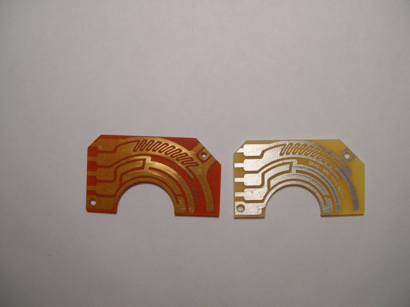
|
|
|
|
| davesprinkle |
Jun 22 2009, 03:37 PM
Post
#14
|
|
Senior Member Group: Members Posts: 720 Joined: 13-October 04 From: Berkeley, CA Member No.: 2,943 Region Association: None |
More pics of initial board installation in this thread over on the club site.
|
|
|
|
| McMark |
Jun 23 2009, 01:00 AM
Post
#15
|
|
914 Freak! Group: Retired Admin Posts: 20,180 Joined: 13-March 03 From: Grand Rapids, MI Member No.: 419 Region Association: None |
(IMG:style_emoticons/default/dry.gif) Posting pictures here is apparently difficult.
|
|
|
|
| Katmanken |
Jun 23 2009, 09:46 AM
Post
#16
|
|
You haven't seen me if anybody asks... Group: Members Posts: 4,738 Joined: 14-June 03 From: USA Member No.: 819 Region Association: Upper MidWest |
Yeah, that's a really good picture on the other site...
It looks just like this....... "This pic shows how the connector sits slightly higher due to the now-loose fit. (The connector should sit flush with the metal base.) Attached File(s) DSCN3982.JPG ( 722.59K ) Number of downloads: 3" And It won't download.... |
|
|
|
| davesprinkle |
Jun 23 2009, 09:50 AM
Post
#17
|
|
Senior Member Group: Members Posts: 720 Joined: 13-October 04 From: Berkeley, CA Member No.: 2,943 Region Association: None |
QUOTE(McMark @ Jun 23 2009, 12:00 AM) No, not difficult. Just frustrating. Two sites, same content, same users. It's easier to post a link than to redo the whole thread. Whatever, here ya go... First, drill out the hole for the factory rivet to 3/32". The rivet hole in the new board is sized for a 3/32" pop rivet, which will be included with the board. For those who have forgotten what a drill-bit looks like, here is a pic: Attached image(s) 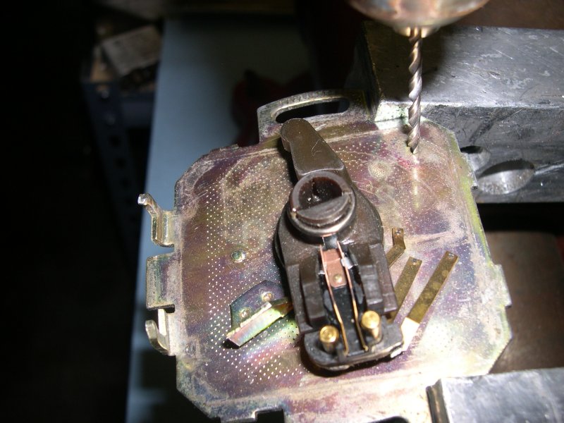
|
|
|
|
| davesprinkle |
Jun 23 2009, 09:51 AM
Post
#18
|
|
Senior Member Group: Members Posts: 720 Joined: 13-October 04 From: Berkeley, CA Member No.: 2,943 Region Association: None |
A business card makes a good ramp for getting the wipers onto the board.
Attached image(s) 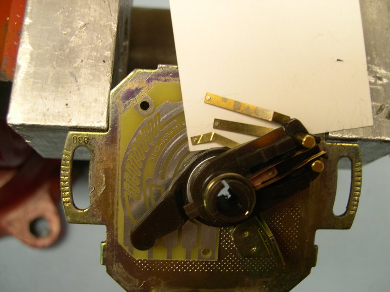
|
|
|
|
| davesprinkle |
Jun 23 2009, 09:51 AM
Post
#19
|
|
Senior Member Group: Members Posts: 720 Joined: 13-October 04 From: Berkeley, CA Member No.: 2,943 Region Association: None |
Here's a pic of the board with the business card removed. No rivet yet.
Attached image(s) 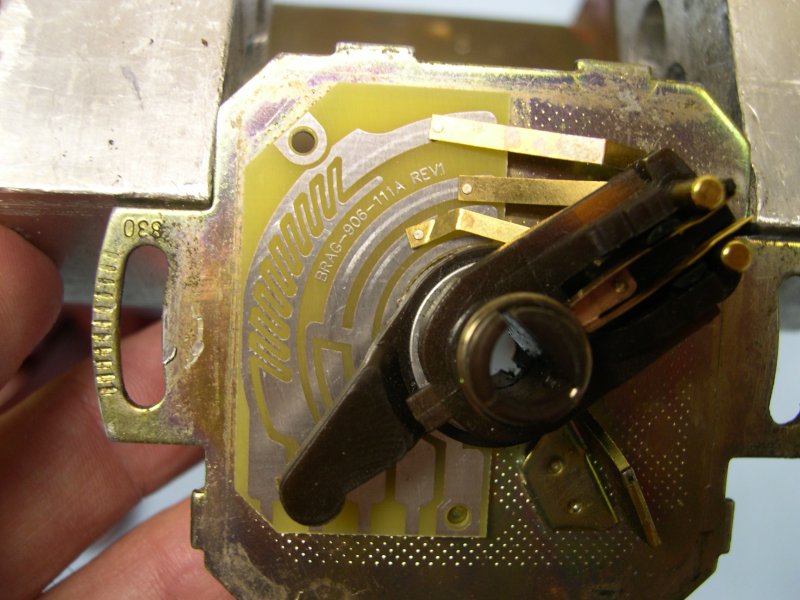
|
|
|
|
| davesprinkle |
Jun 23 2009, 09:54 AM
Post
#20
|
|
Senior Member Group: Members Posts: 720 Joined: 13-October 04 From: Berkeley, CA Member No.: 2,943 Region Association: None |
Rivet installed. I would urge you to fend off the temptation to step up to a 1/8" diameter rivet. The larger head will short out the trace on the board. The correct rivet will be included with the board. Use it.
Attached image(s) 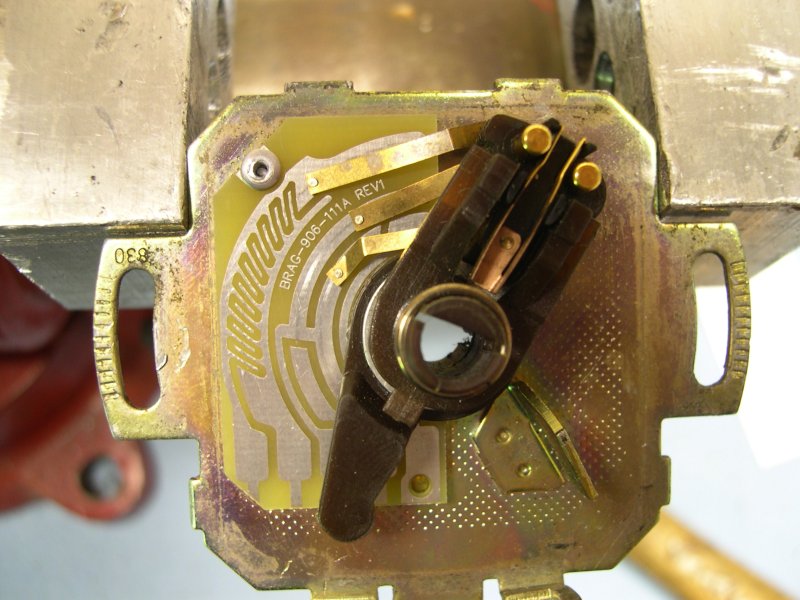
|
|
|
|
|
2 User(s) are reading this topic (2 Guests and 0 Anonymous Users)
0 Members:

|
Lo-Fi Version | Time is now: 9th June 2026 - 06:57 PM |
Invision Power Board
v9.1.4 © 2026 IPS, Inc.