|
|
|
Porsche, and the Porsche crest are registered trademarks of Dr. Ing. h.c. F. Porsche AG.
This site is not affiliated with Porsche in any way. Its only purpose is to provide an online forum for car enthusiasts. All other trademarks are property of their respective owners. |
|
|


| Jakeodoule |
 Sep 18 2009, 11:06 PM Sep 18 2009, 11:06 PM
Post
#1
|
|
Member  Group: Members Posts: 353 Joined: 10-October 08 From: Des Moines Iowa Member No.: 9,630 Region Association: Pacific Northwest |
After reading lots of post on measuring deck height, as well as searching the internet on ways to measure it. I thought there has to be an easier way…
I made a plate that fits on the cylinder. Make sure it’s a good thick plate. I then drilled holes right above the outer part of the bore on both sides. Bolt it down tight. 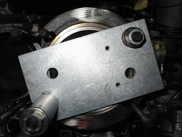 Then I just zeroed out the digital caliper on the upper ring of the cylinder. I checked zero on each side of the plate to make sure its flat. 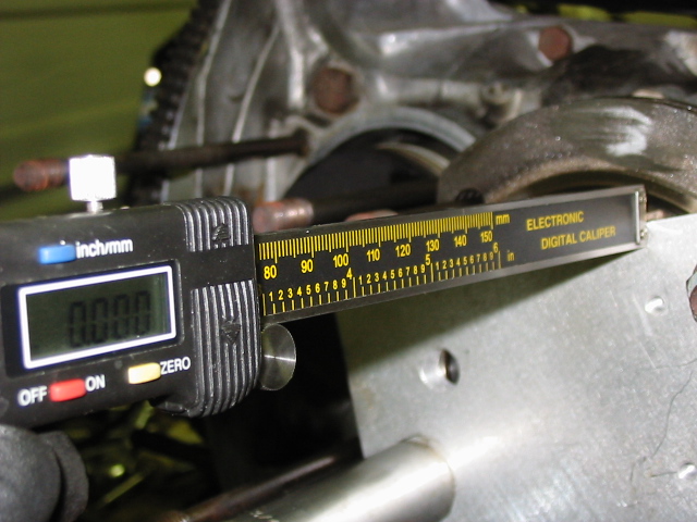 Moved it to one of the piston holes that I drilled. Pushed the caliper end into the bore and turned the cylinder through…. Then I took a reading off the caliper. It only pushes the caliper in to the point of your deck height. 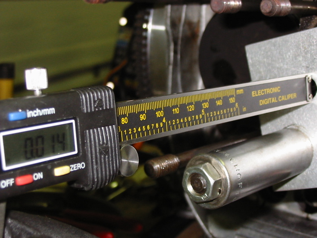 You have to keep the caliper straight! But I took 4 or 5 readings on each side of the piston and each time I came within .0005 of the last reading. This seems rather simple to me as you do not need to find TDC. Just turn the crank till the piston rises and falls a little bit. In between you just shove the end of the caliper in and let the piston push the caliper shaft up till the piston drops back down and that’s your deck height… I also saw many posts that said you only had to measure 1 cylinder. Thats bogus because 1 one my cylinders was .009 thou off from the others. I would measure each one if I were you. Also if you don't have any rings in you need to be careful about the piston being tilted a bit. So I just averaged the readings from side to side. I’m sure I’ve done something that I will be flamed about by all the professional motor builders, but it seems to work for me. I have thick skin so tell me what I did wrong…. |
   |

 
|
  |
Replies(1 - 13)
| McMark |
Sep 18 2009, 11:18 PM
Post
#2
|
|
914 Freak! Group: Retired Admin Posts: 20,180 Joined: 13-March 03 From: Grand Rapids, MI Member No.: 419 Region Association: None |
Look like mine, though I use a dial indicator.
Nice job! |
|
|
|
| Todd Enlund |
Sep 19 2009, 01:37 AM
Post
#3
|
|
Resident Photoshop Guru Group: Members Posts: 3,251 Joined: 24-August 07 From: Laurelhurst (Portland), Oregon Member No.: 8,032 Region Association: Pacific Northwest |
Nice! The only thing I have to add is that it will only work with flat top pistons. You'd have to modify the procedure a bit for dished or domed.
|
|
|
|
| ArtechnikA |
Sep 19 2009, 06:47 AM
Post
#4
|
|
rich herzog Group: Members Posts: 7,390 Joined: 4-April 03 From: Salted Roads, PA Member No.: 513 Region Association: None |
QUOTE(Jakeodoule @ Sep 19 2009, 01:06 AM)  I also saw many posts that said you only had to measure 1 cylinder. Thats bogus because 1 one my cylinders was .009 thou off from the others. I would measure each one if I were you. Always good practice to check them all. But the process depends on what you've done before. You can check one _if_ in the building process you have previously already verified all the crankshaft centerline-to-cylinder mating surface dimensions, the individual crank throws, the connecting rod center-to-center lengths, the individual piston pin-to-deck dimensions, and (most likely to be an issue with available parts...) cylinder length from lower sealing surface to head mating surface. Deck height measurement is kind of a final check for all that stuff. If you're finding a cylinder to cylinder difference at deck height measurement time, you have to go back and find the cause, and fix that. I like the method of using the caliper as a 'telltale' that the piston moves rather than needing to rely on TDC and measuring that. Although in practice, so many things rely on TDC it's something I'd like to verify early and mark (or use a reference like a degree wheel). With a hole in the plate above the point of interest on the piston you could still poke the depth stem of the caliper through the plate for mild domes. If you have pistons with domes that extend above the cylinder mating surface, you're back to the traditional method... |
|
|
|
| DNHunt |
Sep 19 2009, 06:48 AM
Post
#5
|
|
914 Wizard? No way. I got too much to learn. Group: Members Posts: 4,099 Joined: 21-April 03 From: Gig Harbor, WA Member No.: 598 |
That's great, but, I think you need to find TDC. That sure is a lot simpler than the way I did it.
Dave |
|
|
|
| VaccaRabite |
Sep 19 2009, 11:05 AM
Post
#6
|
|
En Garde! Group: Admin Posts: 13,752 Joined: 15-December 03 From: Dallastown, PA Member No.: 1,435 Region Association: MidAtlantic Region |
Eh, why go through all the trouble with a caliper like that when you can just use a dial indicator or use feeler gauges.
Given that a minute angle on the caliper will kill any accuracy variance VS feeler gauge, isn't it easier to use a feeler? If you need the number to the nearest .001, the only way you are really going to get it is with a dial indicator. The only way to get the caliper accurate would be to mount it on a jig, and at that point you have turned it into a dial indicator for all intents and purposes. Zach |
|
|
|
| ME733 |
Sep 19 2009, 12:00 PM
Post
#7
|
|
Senior Member Group: Members Posts: 842 Joined: 25-June 08 From: Atlanta Ga. Member No.: 9,209 Region Association: South East States |
QUOTE(Jakeodoule @ Sep 19 2009, 01:06 AM) After reading lots of post on measuring deck height, as well as searching the internet on ways to measure it. I thought there has to be an easier way… I made a plate that fits on the cylinder. Make sure it’s a good thick plate. I then drilled holes right above the outer part of the bore on both sides. Bolt it down tight. Then I just zeroed out the digital caliper on the upper ring of the cylinder. I checked zero on each side of the plate to make sure its flat. Moved it to one of the piston holes that I drilled. Pushed the caliper end into the bore and turned the cylinder through…. Then I took a reading off the caliper. It only pushes the caliper in to the point of your deck height. You have to keep the caliper straight! But I took 4 or 5 readings on each side of the piston and each time I came within .0005 of the last reading. This seems rather simple to me as you do not need to find TDC. Just turn the crank till the piston rises and falls a little bit. In between you just shove the end of the caliper in and let the piston push the caliper shaft up till the piston drops back down and that’s your deck height… I also saw many posts that said you only had to measure 1 cylinder. Thats bogus because 1 one my cylinders was .009 thou off from the others. I would measure each one if I were you. Also if you don't have any rings in you need to be careful about the piston being tilted a bit. So I just averaged the readings from side to side. I’m sure I’ve done something that I will be flamed about by all the professional motor builders, but it seems to work for me. I have thick skin so tell me what I did wrong…. (IMG:style_emoticons/default/popcorn[1].gif) after measuring each cylinder barrell for O.A.L.....which you apparently did (over all length) mock up (install the cylinders...torqued up (with spacers as required for the head studs). ...Place a machinest stright edge across the top of the installed cylinders...then you can easily measure which cylinder(s) are not level with each other....You may find a slight height difference. IF you do , just ...LAP THAT CYLINDER BARRELL (on an absolutely flat steel surface). to the PERFECT height for that cylinder position...(obviously rechecked toward perfection)....NOW your heads (sealing surface ) will sit perfectly flat...across the barrells. (IMG:style_emoticons/default/popcorn[1].gif) |
|
|
|
| Drums66 |
Sep 19 2009, 02:08 PM
Post
#8
|
|
914 Rudiments Group: Members Posts: 5,321 Joined: 15-January 03 From: Coronado,Cali Member No.: 151 Region Association: Southwest Region |
QUOTE(Todd Enlund @ Sep 19 2009, 12:37 AM) Nice! The only thing I have to add is that it will only work with flat top pistons. You'd have to modify the procedure a bit for dished or domed. Yeah....that's why the dial indicator! (IMG:style_emoticons/default/confused24.gif) (IMG:style_emoticons/default/idea.gif) (IMG:style_emoticons/default/popcorn[1].gif) |
|
|
|
| Cap'n Krusty |
Sep 19 2009, 02:33 PM
Post
#9
|
|
Cap'n Krusty Group: Members Posts: 10,794 Joined: 24-June 04 From: Santa Maria, CA Member No.: 2,246 Region Association: Central California |
QUOTE(ME733 @ Sep 19 2009, 11:00 AM) QUOTE(Jakeodoule @ Sep 19 2009, 01:06 AM) After reading lots of post on measuring deck height, as well as searching the internet on ways to measure it. I thought there has to be an easier way… I made a plate that fits on the cylinder. Make sure it’s a good thick plate. I then drilled holes right above the outer part of the bore on both sides. Bolt it down tight. Then I just zeroed out the digital caliper on the upper ring of the cylinder. I checked zero on each side of the plate to make sure its flat. Moved it to one of the piston holes that I drilled. Pushed the caliper end into the bore and turned the cylinder through…. Then I took a reading off the caliper. It only pushes the caliper in to the point of your deck height. You have to keep the caliper straight! But I took 4 or 5 readings on each side of the piston and each time I came within .0005 of the last reading. This seems rather simple to me as you do not need to find TDC. Just turn the crank till the piston rises and falls a little bit. In between you just shove the end of the caliper in and let the piston push the caliper shaft up till the piston drops back down and that’s your deck height… I also saw many posts that said you only had to measure 1 cylinder. Thats bogus because 1 one my cylinders was .009 thou off from the others. I would measure each one if I were you. Also if you don't have any rings in you need to be careful about the piston being tilted a bit. So I just averaged the readings from side to side. I’m sure I’ve done something that I will be flamed about by all the professional motor builders, but it seems to work for me. I have thick skin so tell me what I did wrong…. (IMG:style_emoticons/default/popcorn[1].gif) after measuring each cylinder barrell for O.A.L.....which you apparently did (over all length) mock up (install the cylinders...torqued up (with spacers as required for the head studs). ...Place a machinest stright edge across the top of the installed cylinders...then you can easily measure which cylinder(s) are not level with each other....You may find a slight height difference. IF you do , just ...LAP THAT CYLINDER BARRELL (on an absolutely flat steel surface). to the PERFECT height for that cylinder position...(obviously rechecked toward perfection)....NOW your heads (sealing surface ) will sit perfectly flat...across the barrells. (IMG:style_emoticons/default/popcorn[1].gif) "Lap that cylinder barrel"? What, your arms, hands, and eyes equal the precision of a lathe or vertical mill? Most of us can't hold ten thousandths tolerances by hand, and I doubt you can either. Yet another myth that seems to never go away. The Cap'n |
|
|
|
| ME733 |
Sep 19 2009, 05:31 PM
Post
#10
|
|
Senior Member Group: Members Posts: 842 Joined: 25-June 08 From: Atlanta Ga. Member No.: 9,209 Region Association: South East States |
(IMG:style_emoticons/default/popcorn[1].gif) Well capt. crusty I have noted on several occasions now that YOU have made comments reguarding ...LAPPING...of . various parts. Specifically ..HEAD sealing surfaces and The tops of CYLINDERS. you have stated Previously you have 36 years of engine building experience. I would suggest that you have only assembly experience. IT is IMPOSSABLE to blueprint, build an engine to the closest tollarences of accuracy without using LAPPING (of various parts) as a TECHNIQUE to get to that point.....I suppose you never have LAPPED valves into their seats ...while in the process of doing a valve job. I guess you just bolt up whatever the machine shop gives you to assemble. The technique for getting the cylinder barrell heights perfectly level was explained. maybe it does take a certain level of mechanical appitude to LAP components but it is necessary, required, to get it perfect. try cutting off just .0005ths ..1/2 ths..or .001ths from the top of a cylinder barrell. IT takes a TOOL ROOM lathe for that level of accuracy.(I could have said .002 or.005ths ) which would be difficult ( impossable?) even for the best machinists. ..so how about S.ing T. F.up about this technique, and method which you apparently know nothing about, have never used, and apparently will not accept as a, technique, method , of engine BUILDING. Capt. Crusty I appreciate all that you do on this site. and your knowledge of 914 stuff is incredable. thanks. Murray Mcafee ..Black Forest Engineering. (retired) (IMG:style_emoticons/default/popcorn[1].gif)
|
|
|
|
| McMark |
Sep 20 2009, 12:35 AM
Post
#11
|
|
914 Freak! Group: Retired Admin Posts: 20,180 Joined: 13-March 03 From: Grand Rapids, MI Member No.: 419 Region Association: None |
Cap'n, he's not talking about lapping the cylinder to the head. He's talking about making the cylinders absolutely equal, so there are no compression leaks. (IMG:style_emoticons/default/tongue.gif)
|
|
|
|
| ArtechnikA |
Sep 20 2009, 07:05 AM
Post
#12
|
|
rich herzog Group: Members Posts: 7,390 Joined: 4-April 03 From: Salted Roads, PA Member No.: 513 Region Association: None |
QUOTE(McMark @ Sep 20 2009, 02:35 AM) Cap'n, he's not talking about lapping the cylinder to the head. He's talking about making the cylinders absolutely equal, so there are no compression leaks. Yes, that's clear enough. And it must be done to an amount exactly equal to the other cylinder on that side, and absolutely parallel to the case deck and head sealing plane - and the other cylinder. I believe it can be done by a patient, trained craftsman with a big surface plate. The more you try to take off the harder it is to stay absolutely square. .009 is a bunch to try to do by hand on a steel cylinder - and if the 'off' one is .009 short, you're doing that to the other three and they all have to be square and true. It's a judgment call. If you don't have the big surface plate, the fine abrasives, and the gauges to verify that your work is absolutely true, square, and to the required dimension, nor the time it takes or patience to work slow and check often, you're probably better off having the work done by a machinist with the right tools for the job. (I am not a machinist so I don't know of that'd be a lathe, a mill, or something else...) If you have access to a machinist you can trust. Those of you who think it's easy to remove exactly .009" all across a big steel cylinder, square to the bore and parallel to the lower sealing cylinder, using the tools you've got - give it a try. It's hard. Mr Mcafee -- I believe you can do it. I actually believe JL (Cap'n Krusty) could do it if he had to. But I do not believe it should be touted as the technique of choice for the twice-a-lifetime DIY engine builder... |
|
|
|
| ME733 |
Sep 20 2009, 09:49 AM
Post
#13
|
|
Senior Member Group: Members Posts: 842 Joined: 25-June 08 From: Atlanta Ga. Member No.: 9,209 Region Association: South East States |
(IMG:style_emoticons/default/popcorn[1].gif) Yes , well , If the cylinder was ... .009ths short. ...then place a .010ths barrell spacer / shim under that cylinder next to the case.....Now you have that cylinder....001 ths... too tall. At that point ..most assemblers could live with the results.(and I,m sure it would work). Lapping off .001ths from the top of the cylinder barrell is easy. THIS IS WHY it is important to measure the O.A.L. of each cylinder barrell ,and having done so, position the cylinders in the case(marked for replication), torque them down, place a machinest stright edge across the cylinders and check the level.(this is done with all the necessary barrell shimms for sealing the cylinders to the case installed on the barrells ..The thickness of these spacers/shimms can also be inconsistant . Now you are getting to what I call a "stack-up" of dimensions. Because this method will account for the distortion Of and machining errors of the crankcase cylinder barrell support flange. We are using engine blocks that have..."billions and billions?".(thank you Carl Sagen) of heat cycles so the machined surfaces are just not perfect anymore. Getting the barrell tops (sealing surfaces) level with each other IS THE GOAL . So the head is not warped into place when torqued down. LAPPING OFF .001 to .003ths from the tops of CAST steel or CAST iron barrells is not that difficult. When done, YOU KNOW the heads will be seated ,sealed without having to "GRONK '' them into place. (IMG:style_emoticons/default/popcorn[1].gif)
|
|
|
|
| ArtechnikA |
Sep 20 2009, 10:06 AM
Post
#14
|
|
rich herzog Group: Members Posts: 7,390 Joined: 4-April 03 From: Salted Roads, PA Member No.: 513 Region Association: None |
QUOTE(ME733 @ Sep 20 2009, 11:49 AM) ...THIS IS WHY it is important to measure the O.A.L. of each cylinder barrell I believe I mentioned that earlier... QUOTE ...having done so, position the cylinders in the case(marked for replication) a good idea. If there's any variance, you might be able to move a 'taller' cylinder to a hole with a 'lower' spigot.QUOTE We are using engine blocks that have..."billions and billions?".(thank you Carl Sagen) of heat cycles so the machined surfaces are just not perfect anymore. Why do we put up with this? Why don't we have the cylinder spigot trued to the crankshaft centerline so it _is_ perfect? We're going to use a base shim anyway... QUOTE Getting the barrell tops (sealing surfaces) level with each other IS THE GOAL. I agree it's _a_ goal. Also be nice to know that the base surfaces at the case were equal, normal to the crankshaft centerline, and identical side-to-side... And to check that some DAPO had not earlier boogered a flycut in the heads so they, too, had identical depths... QUOTE LAPPING OFF .001 to .003ths from the tops of CAST steel or CAST iron barrells is not that difficult. I believe you have the tools and experience. There are people who are going to read this thread and think they can do it with Home Depot sandpaper on a card table. |
|
|
|
|
1 User(s) are reading this topic (1 Guests and 0 Anonymous Users)
0 Members:

|
Lo-Fi Version | Time is now: 1st July 2025 - 12:27 AM |
Invision Power Board
v9.1.4 © 2025 IPS, Inc.