|
|
|
Porsche, and the Porsche crest are registered trademarks of Dr. Ing. h.c. F. Porsche AG.
This site is not affiliated with Porsche in any way. Its only purpose is to provide an online forum for car enthusiasts. All other trademarks are property of their respective owners. |
|
|


| jk76.914 |
 Jan 30 2010, 11:57 AM Jan 30 2010, 11:57 AM
Post
#1
|
|
Senior Member  Group: Members Posts: 809 Joined: 12-April 05 From: Massachusetts Member No.: 3,925 Region Association: North East States |
I collected a number of MPS over a couple of years. Most held vacuum, some did not. I measured inductance vs. vacuum on those that I could, but then took all of them apart (except one brand new one).
The is a lot of variety in the diaphrams, probably because they get replaced when virtually every MPS is rebuilt. The photo below shows four diaphrams. I'll follow with descriptions and observations... 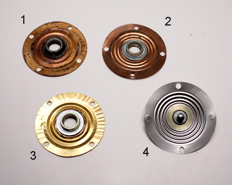 #1- copper, 2 pleats. This came from a rebuilt MPS that was in a pond or river for some time. There was actually sand in it, along with tiny aquatic snail shells of some sort, and the copper was pretty much green. This diaphram was ruptured. The workmanship is very good, and the alloy is idential to stock (see chart below). The threaded bushing looks like stock in design and attachment. #2- copper, 3 pleats. This is a stock diaphram from a riveted MPS. It is ruptured. #3- brass, 2 pleats. This is from a rebuilt MPS. I have three of these diaphrams, all similar. This MPS was freshly rebuilt in a rebuilder's box. Looked like new with fresh paint and plastic cap on vacuum port, but it leaked slightly. You can see why when you look at the ripples in that flange. The O.D. looks like it was cut out by hand with tin snips, and the threaded bushing was taken from a stock diaphram and soldered by hand into place. At the bottom in the picture, you can see that the flange is pretty smooth- that's where I tapped it out with a machinist's hammer on an anvil. I have no doubt that the leakage was from around the O.D. of the diaphram, and that tapping it out would probably fix it. This material (brass, see chart below) is stiffer and thicker than any of the rest. It would add quite a bit of spring tension to the mass-spring-damper system. In general, I rate the workmanship on this as "crappy", though maybe you could get a running car out of it. #4- stainless steel, 3 pleats. This one is a bit of an enigma. It is identical to stock except that it is made from stainless (see chart below). The workmanship is perfect. It is from a rebuilt MPS. Interestingly, it is the MOST COMPLIANT of all of them, while most steel ones are reported to be stiffer. The other part of the enigma- the aneroid cells from this MPS are also stainless- same alloy. My suspicion is that this is a late Bosch rebuilt. Who else would make stainless cells, because the cells don't fail very often, so there are lots of spares available out there, and the cells are pretty complicated to make... *** EDITED *** Materials. I measured alloy composition at work using an X-Ray Fluorescence analyzer. This machine is very precise, but it has limits to the range of elements that it can detect. Unfortunately, it cannot detect Beryllium (Be), and it is likely that the stock (at least) diaphram contains Be to harden and strengthen it. You can see a couple of things here though- the stainless diaphram and stainless cells are of exactly the same composition- nickel-chromium stainless steel. The nickel explains why they are slightly magnetic, as many stainless alloys are not. *** 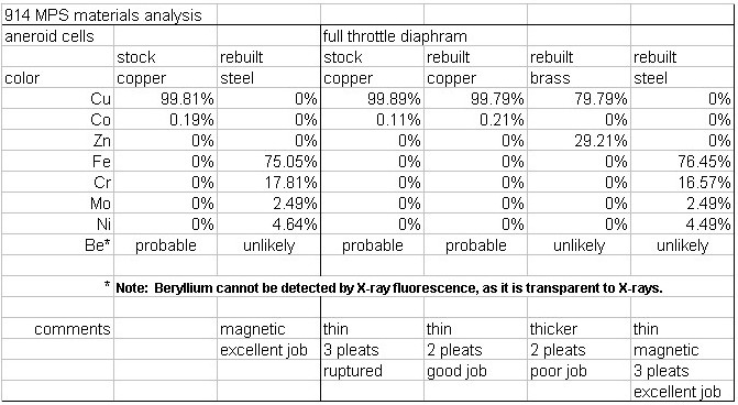 Conclusions (really opinions) - The diaphram was put in there (early VW D-jets did not have one) to provide altitude compensation and to soften transition from leaner (high vacuum) to richer (low vacuum) regions. Early D-Jets had a separate unit with a diaphram and a switch to inform the ECU to richen the mixture at low vacuum. Cost reduction may have been a third reason- eliminating the separate unit, wiring, vacuum hose, etc. Anyway, this switch was either on or off, no soft transition. The MPS had only 2 aneroid cells and no diaphram, and its inductance curve was essentially a straight line from 0" to 25". There was no mixture compensation for altitude with this arrangement. I'm thinking that the lower the stiffness of the diaphram, the more consistency in the setup and responsiveness, while both of these objectives are met. By maximizing compliance of the diaphram, the springs acting in the system are mainly the coil spring and the leaf springs that act to locate the armature. My stainless diaphram is the most compliant, but there is another feature of steel (if I remember correctly) that adds to the argument that this is a late Bosch design- steel has a much higher Youngs modulus than copper. The higher the Youngs modulus, the greater the fatigue resistance, and the vastly most common failure mode of the MPS is fatigue failure. Could this have been a Bosch attempt to solve a reliability problem, even as the technology was being superceded by more modern ones? Since the cells are also subject to fatigue, would they have switched them over at the same time? I am planning on assembling my own personal MPS using the stainless parts, and seeing how close I can tune it to my engine. There are lots of other parts in the MPS that I've formed opinions about, but I'll hold off for now. These are my own opinions, which may not be popular, so BLAST AWAY!! (eye candy below)  |
   |

 
|
  |
Replies
| pbanders |
Mar 1 2010, 11:14 AM
Post
#2
|
|
Senior Member Group: Members Posts: 988 Joined: 11-June 03 From: Scottsdale, AZ Member No.: 805 Region Association: Southwest Region |
It would be great if we could get Bosch to supply a run of replacement diaprhagms.
I might point out that even if a replacement diaphragm were available, that rebuilding and calibrating the MPS isn't a trival thing. Here are the steps as I see it: 1. Remove the epoxy from the full load stop - don't attempt to remove the full load stop yet. 2. Drill out the case rivets to remove the top. 3. Using a 3/8" tip flat screwdriver (filed to fit the slot tightly), drive the full-load stop through and out of the top half of the case. Don't try to back it out, as there is epoxy holding the threads. Heat and WD-40 will help this operation. You may want to break it loose before drilling out the case rivets first, as it may make it easier to secure the MPS. 4. Remove the old diaphragm and remove the adjuster assembly from it, reinstall in the new diaphragm to approximately the same depth. Use a vernier to set it exactly. 5. Clean out the interior of the MPS with contact cleaner. 6. Install the diaphragm. Assuming we don't have a supply of new gaskets, install the old gasket, and use a thin layer of heavy grease to seal it. 7. Tap the case and bore the top to accept screws to secure the top. 8. Install the top, leave the full-load stop out for now. 9. Using the tables on my MPS page (see my sig for links) and a Wavetek LCR55 meter, set the inner and outer adjusters as described on the page. Install the full-load stop as described on the page. 10. At this point, the MPS is approximately adjusted and should work. To properly optimize the adjustment, you'll need to set the part load and full load mixtures using a dynamometer and a gas analyzer. Suggested settings for stock 2.0L motors are part-load (i.e. 2500 rpm, low throttle angle) at a CO of 2.5% to 3.0%, and a full-load (i.e. 4000 rpm, wide-open throttle angle) at a CO of 4.5% to 5.0%. To those out there who have done this before, please feel free to edit and correct this procedure as required. |
|
|
|
Posts in this topic
jk76.914 MPS- delving into it's secrets? Jan 30 2010, 11:57 AM Bartlett 914 Great Job! That is interesting information. If... Jan 30 2010, 12:32 PM underthetire Good work! It was always assumed it was BeCu, ... Jan 30 2010, 01:20 PM
 jk76.914
Good work! It was always assumed it was BeCu,... Jan 30 2010, 04:14 PM detoxcowboy "This came from a rebuilt MPS that was in a p... Jan 30 2010, 11:19 PM Dave_Darling They gave it the "float test"? ;)
(Mus... Jan 31 2010, 01:21 AM 914Sixer Of the MPS I have taken apart, I have only seen ve... Jan 31 2010, 08:08 AM pbanders Wow, really great info! With your permission a... Feb 1 2010, 11:11 AM jk76.914
Wow, really great info! With your permission ... Feb 1 2010, 08:46 PM pbanders
I measured several (maybe 6) aneroid cells sets u... Feb 2 2010, 09:25 AM realred914
Wow, really great info! With your permission... Dec 7 2010, 02:22 PM mtndawg This information is great.This is what I've of... Feb 1 2010, 04:31 PM jk76.914 I'm back. I looked in to this, and unfortunat... Feb 9 2010, 05:49 AM ArtechnikA
...anyone know how I can go in and edit that post... Feb 9 2010, 06:17 AM pbanders I used to do a lot of surface analysis when I work... Feb 9 2010, 08:57 AM pbanders
I used to do a lot of surface analysis when I wor... Feb 9 2010, 09:53 AM pbanders Also seems like once we get a material and a desig... Feb 9 2010, 10:02 AM Bleyseng From RustyWa years ago in a PM to me.
"You ... Feb 9 2010, 10:47 AM pbanders
From RustyWa years ago in a PM to me.
"You... Feb 9 2010, 10:53 AM Bleyseng
From RustyWa years ago in a PM to me.
"Yo... Feb 9 2010, 11:17 AM Jeff Bowlsby As easy as it would be to make it from pure copper... Feb 9 2010, 02:36 PM pbanders Jeff's right, pure Cu is very soft. Ever hear ... Feb 9 2010, 05:19 PM jk76.914 The Niton XL-800 is also an X-ray fluroescence ins... Feb 9 2010, 07:08 PM Bleyseng yeah but, Eric's testing showed no Be just Al,... Feb 9 2010, 07:20 PM jk76.914 Quick update. I did the crappy brass characteriza... Feb 11 2010, 04:59 AM jk76.914 Yesterday during lunch, we tried to press apart a ... Feb 20 2010, 11:43 AM ArtechnikA
So we sectioned it. Take a look....
As you can ... Feb 20 2010, 02:16 PM underthetire did the ring seem hard yet gummy when you cut it? ... Feb 20 2010, 12:39 PM kwales I think yer making this too hard.
I agree with th... Feb 20 2010, 05:19 PM jk76.914
I think yer making this too hard.
I agree with t... Feb 21 2010, 07:43 AM 76-914 Great stuff here. I'll bet ya'll will have... Feb 20 2010, 06:58 PM pbanders Great stuff, a few comments. One, the design of th... Feb 21 2010, 09:23 AM jk76.914
Great stuff, a few comments. One, the design of t... Feb 21 2010, 12:13 PM kwales I think they make the PEM's out of the stuff t... Feb 21 2010, 12:05 PM McMark You guys are awesome for researching this... :notw... Feb 21 2010, 12:09 PM jk76.914 OK. I took some more photos. These three are cop... Feb 21 2010, 01:49 PM jk76.914 Picked up a -010 MPS this week, allegedly from a V... Feb 27 2010, 04:57 PM ArtechnikA
The diaphram hub is idential to stock, which I... Feb 28 2010, 05:16 AM McMark :trophy: :notworthy: Feb 27 2010, 11:43 PM rick 918-S Love this science stuff! Feb 28 2010, 12:23 AM 914Sixer Really amazing reading!! :Qarl: Feb 28 2010, 07:35 AM Thomas J Bliznik
Really amazing reading!! :Qarl:
:ag... Feb 28 2010, 08:30 AM jk76.914
Really amazing reading!! :Qarl:
:a... Feb 28 2010, 11:33 AM pbanders
Anybody have any connections at Bosch?
FWIW, th... Mar 1 2010, 11:20 AM pbanders FYI, are others aware of the Bosch Classic web sho... Mar 1 2010, 11:29 AM pbanders FWIW, I sent an email to the guy in Bosch Germany ... Mar 1 2010, 06:02 PM jk76.914
FWIW, I sent an email to the guy in Bosch Germany... Mar 1 2010, 06:30 PM jk76.914 OK, some images from that -010 Volvo MPS. First t... Mar 1 2010, 06:45 PM jk76.914 Nice clean housing. Not perfect, but not bad. Yo... Mar 1 2010, 07:09 PM Bleyseng .
Also found another of those plastic rings... W... Mar 2 2010, 09:21 AM pbanders FYI, I've made some interesting connections at... Mar 3 2010, 10:48 AM pbanders OK, here's a bit more info. There's a news... Mar 3 2010, 11:14 AM kwales While you are on a roll,
Howsabout fuel injectors... Mar 3 2010, 02:18 PM SirAndy
Howsabout fuel injectors.......
:agree:
We sh... Mar 3 2010, 02:33 PM pbanders
Howsabout fuel injectors.......
:agree:
We s... Mar 3 2010, 02:51 PM jk76.914 Brad's link links to Bosch Traditions, which i... Mar 3 2010, 06:55 PM jk76.914 Did anybody say throttle position sensor?
Here... Mar 3 2010, 07:17 PM computers4kids Yikes...that's $218 US dollars :blink:
... Mar 3 2010, 07:39 PM jk76.914
Yikes...that's $218 US dollars :blink: ... Mar 3 2010, 08:05 PM computers4kids
[quote name='computers4kids' post='1281997' date=... Mar 3 2010, 10:26 PM jk76.914 Nevermind. I found the english version at eBay-UK... Mar 3 2010, 08:55 PM pbanders Yeah, I should have been more clear. I knew the ha... Mar 3 2010, 09:39 PM Bleyseng Maybe I can send them the box of 50 dead MPSs siit... Mar 4 2010, 01:24 AM jk76.914 Too bad you can't just get a kit. Diaphram, o... Mar 4 2010, 04:34 AM McMark Jim, tuning is the real issue with a home rebuild ... Mar 4 2010, 12:33 PM Bleyseng
Jim, tuning is the real issue with a home rebuild... Mar 5 2010, 09:58 AM jk76.914
Jim, tuning is the real issue with a home rebuil... Mar 5 2010, 04:56 PM Larouex
[quote name='Bleyseng' post='1282691' date='Mar 5... Mar 8 2010, 09:29 AM Bleyseng
[quote name='Bleyseng' post='1282691' date='Mar ... Mar 8 2010, 10:52 AM pbanders
First you weld a "bung" onto the exhaus... Mar 8 2010, 11:05 AM jk76.914 I know. But I also I think there's an opportu... Mar 4 2010, 07:53 PM mtndawg I sent an email to Bosch via the Traditions web si... Mar 5 2010, 09:46 AM 1988Hawk 4 new 2.0 injectors from Otto, not cheap but reaso... Mar 5 2010, 07:03 PM pbanders Matthias is the same guy I'm communicating wit... Mar 5 2010, 11:06 PM jk76.914 Exchanged emails with Herr Matthias Klumpp at Bosc... Mar 8 2010, 05:24 AM ArtechnikA I would be quite surprised if Bosch made a rebuild... Mar 8 2010, 06:07 AM pbanders
I would be quite surprised if Bosch made a rebuil... Mar 8 2010, 10:36 AM kconway So if Bosch does a rebuild kit over a complete reb... Mar 8 2010, 11:08 AM pbanders
So if Bosch does a rebuild kit over a complete re... Mar 8 2010, 11:18 AM jk76.914
So if Bosch does a rebuild kit over a complete r... Mar 8 2010, 07:49 PM jk76.914
So if Bosch does a rebuild kit over a complete re... Mar 8 2010, 08:04 PM Bleyseng Even when Bosch comes out with a new or rebuilt MP... Mar 8 2010, 09:18 PM 3d914 Any update on this? Curious 914 owners are watchin... Oct 17 2010, 11:13 PM jk76.914
Any update on this? Curious 914 owners are watchi... Oct 18 2010, 03:15 AM trfrick This is what I received from Bosch regarding rebui... Dec 6 2010, 02:25 PM r_towle fantastic news Dec 6 2010, 02:52 PM jk76.914 Well, I guess it's time to get back at this. ... Dec 6 2010, 07:04 PM jk76.914 I've set aside trying to make diaphrams for no... Dec 6 2010, 07:14 PM SirAndy I've set aside trying to make diaphrams for no... Dec 6 2010, 09:50 PM jk76.914 I also toyed with the idea of making a test diaphr... Dec 6 2010, 07:20 PM jk76.914 Here's a loose end from last spring. I dissec... Dec 6 2010, 07:29 PM Bleyseng
Here's a loose end from last spring. I disse... Dec 7 2010, 06:35 AM jk76.914 I know. Something had to give. If I focus on mak... Dec 7 2010, 07:22 AM Bleyseng
I know. Something had to give. If I focus on ma... Dec 7 2010, 08:46 AM realred914 looks like i will will be needing to get my mps cl... Dec 7 2010, 02:29 PM jk76.914
looks like i will will be needing to get my mps c... Dec 7 2010, 08:14 PM 914 shifter diaphram-less MPS that is properly set up with suc... Dec 7 2010, 10:01 PM bandjoey Yes. I've just read this front to back and it... Dec 7 2010, 10:40 PM Bleyseng if you are running a stock rebuild motor setting t... Dec 8 2010, 07:13 AM
jk76.914
Good work! It was always assumed it was BeCu,... Jan 30 2010, 04:14 PM detoxcowboy "This came from a rebuilt MPS that was in a p... Jan 30 2010, 11:19 PM Dave_Darling They gave it the "float test"? ;)
(Mus... Jan 31 2010, 01:21 AM 914Sixer Of the MPS I have taken apart, I have only seen ve... Jan 31 2010, 08:08 AM pbanders Wow, really great info! With your permission a... Feb 1 2010, 11:11 AM jk76.914
Wow, really great info! With your permission ... Feb 1 2010, 08:46 PM pbanders
I measured several (maybe 6) aneroid cells sets u... Feb 2 2010, 09:25 AM realred914
Wow, really great info! With your permission... Dec 7 2010, 02:22 PM mtndawg This information is great.This is what I've of... Feb 1 2010, 04:31 PM jk76.914 I'm back. I looked in to this, and unfortunat... Feb 9 2010, 05:49 AM ArtechnikA
...anyone know how I can go in and edit that post... Feb 9 2010, 06:17 AM pbanders I used to do a lot of surface analysis when I work... Feb 9 2010, 08:57 AM pbanders
I used to do a lot of surface analysis when I wor... Feb 9 2010, 09:53 AM pbanders Also seems like once we get a material and a desig... Feb 9 2010, 10:02 AM Bleyseng From RustyWa years ago in a PM to me.
"You ... Feb 9 2010, 10:47 AM pbanders
From RustyWa years ago in a PM to me.
"You... Feb 9 2010, 10:53 AM Bleyseng
From RustyWa years ago in a PM to me.
"Yo... Feb 9 2010, 11:17 AM Jeff Bowlsby As easy as it would be to make it from pure copper... Feb 9 2010, 02:36 PM pbanders Jeff's right, pure Cu is very soft. Ever hear ... Feb 9 2010, 05:19 PM jk76.914 The Niton XL-800 is also an X-ray fluroescence ins... Feb 9 2010, 07:08 PM Bleyseng yeah but, Eric's testing showed no Be just Al,... Feb 9 2010, 07:20 PM jk76.914 Quick update. I did the crappy brass characteriza... Feb 11 2010, 04:59 AM jk76.914 Yesterday during lunch, we tried to press apart a ... Feb 20 2010, 11:43 AM ArtechnikA
So we sectioned it. Take a look....
As you can ... Feb 20 2010, 02:16 PM underthetire did the ring seem hard yet gummy when you cut it? ... Feb 20 2010, 12:39 PM kwales I think yer making this too hard.
I agree with th... Feb 20 2010, 05:19 PM jk76.914
I think yer making this too hard.
I agree with t... Feb 21 2010, 07:43 AM 76-914 Great stuff here. I'll bet ya'll will have... Feb 20 2010, 06:58 PM pbanders Great stuff, a few comments. One, the design of th... Feb 21 2010, 09:23 AM jk76.914
Great stuff, a few comments. One, the design of t... Feb 21 2010, 12:13 PM kwales I think they make the PEM's out of the stuff t... Feb 21 2010, 12:05 PM McMark You guys are awesome for researching this... :notw... Feb 21 2010, 12:09 PM jk76.914 OK. I took some more photos. These three are cop... Feb 21 2010, 01:49 PM jk76.914 Picked up a -010 MPS this week, allegedly from a V... Feb 27 2010, 04:57 PM ArtechnikA
The diaphram hub is idential to stock, which I... Feb 28 2010, 05:16 AM McMark :trophy: :notworthy: Feb 27 2010, 11:43 PM rick 918-S Love this science stuff! Feb 28 2010, 12:23 AM 914Sixer Really amazing reading!! :Qarl: Feb 28 2010, 07:35 AM Thomas J Bliznik
Really amazing reading!! :Qarl:
:ag... Feb 28 2010, 08:30 AM jk76.914
Really amazing reading!! :Qarl:
:a... Feb 28 2010, 11:33 AM pbanders
Anybody have any connections at Bosch?
FWIW, th... Mar 1 2010, 11:20 AM pbanders FYI, are others aware of the Bosch Classic web sho... Mar 1 2010, 11:29 AM pbanders FWIW, I sent an email to the guy in Bosch Germany ... Mar 1 2010, 06:02 PM jk76.914
FWIW, I sent an email to the guy in Bosch Germany... Mar 1 2010, 06:30 PM jk76.914 OK, some images from that -010 Volvo MPS. First t... Mar 1 2010, 06:45 PM jk76.914 Nice clean housing. Not perfect, but not bad. Yo... Mar 1 2010, 07:09 PM Bleyseng .
Also found another of those plastic rings... W... Mar 2 2010, 09:21 AM pbanders FYI, I've made some interesting connections at... Mar 3 2010, 10:48 AM pbanders OK, here's a bit more info. There's a news... Mar 3 2010, 11:14 AM kwales While you are on a roll,
Howsabout fuel injectors... Mar 3 2010, 02:18 PM SirAndy
Howsabout fuel injectors.......
:agree:
We sh... Mar 3 2010, 02:33 PM pbanders
Howsabout fuel injectors.......
:agree:
We s... Mar 3 2010, 02:51 PM jk76.914 Brad's link links to Bosch Traditions, which i... Mar 3 2010, 06:55 PM jk76.914 Did anybody say throttle position sensor?
Here... Mar 3 2010, 07:17 PM computers4kids Yikes...that's $218 US dollars :blink:
... Mar 3 2010, 07:39 PM jk76.914
Yikes...that's $218 US dollars :blink: ... Mar 3 2010, 08:05 PM computers4kids
[quote name='computers4kids' post='1281997' date=... Mar 3 2010, 10:26 PM jk76.914 Nevermind. I found the english version at eBay-UK... Mar 3 2010, 08:55 PM pbanders Yeah, I should have been more clear. I knew the ha... Mar 3 2010, 09:39 PM Bleyseng Maybe I can send them the box of 50 dead MPSs siit... Mar 4 2010, 01:24 AM jk76.914 Too bad you can't just get a kit. Diaphram, o... Mar 4 2010, 04:34 AM McMark Jim, tuning is the real issue with a home rebuild ... Mar 4 2010, 12:33 PM Bleyseng
Jim, tuning is the real issue with a home rebuild... Mar 5 2010, 09:58 AM jk76.914
Jim, tuning is the real issue with a home rebuil... Mar 5 2010, 04:56 PM Larouex
[quote name='Bleyseng' post='1282691' date='Mar 5... Mar 8 2010, 09:29 AM Bleyseng
[quote name='Bleyseng' post='1282691' date='Mar ... Mar 8 2010, 10:52 AM pbanders
First you weld a "bung" onto the exhaus... Mar 8 2010, 11:05 AM jk76.914 I know. But I also I think there's an opportu... Mar 4 2010, 07:53 PM mtndawg I sent an email to Bosch via the Traditions web si... Mar 5 2010, 09:46 AM 1988Hawk 4 new 2.0 injectors from Otto, not cheap but reaso... Mar 5 2010, 07:03 PM pbanders Matthias is the same guy I'm communicating wit... Mar 5 2010, 11:06 PM jk76.914 Exchanged emails with Herr Matthias Klumpp at Bosc... Mar 8 2010, 05:24 AM ArtechnikA I would be quite surprised if Bosch made a rebuild... Mar 8 2010, 06:07 AM pbanders
I would be quite surprised if Bosch made a rebuil... Mar 8 2010, 10:36 AM kconway So if Bosch does a rebuild kit over a complete reb... Mar 8 2010, 11:08 AM pbanders
So if Bosch does a rebuild kit over a complete re... Mar 8 2010, 11:18 AM jk76.914
So if Bosch does a rebuild kit over a complete r... Mar 8 2010, 07:49 PM jk76.914
So if Bosch does a rebuild kit over a complete re... Mar 8 2010, 08:04 PM Bleyseng Even when Bosch comes out with a new or rebuilt MP... Mar 8 2010, 09:18 PM 3d914 Any update on this? Curious 914 owners are watchin... Oct 17 2010, 11:13 PM jk76.914
Any update on this? Curious 914 owners are watchi... Oct 18 2010, 03:15 AM trfrick This is what I received from Bosch regarding rebui... Dec 6 2010, 02:25 PM r_towle fantastic news Dec 6 2010, 02:52 PM jk76.914 Well, I guess it's time to get back at this. ... Dec 6 2010, 07:04 PM jk76.914 I've set aside trying to make diaphrams for no... Dec 6 2010, 07:14 PM SirAndy I've set aside trying to make diaphrams for no... Dec 6 2010, 09:50 PM jk76.914 I also toyed with the idea of making a test diaphr... Dec 6 2010, 07:20 PM jk76.914 Here's a loose end from last spring. I dissec... Dec 6 2010, 07:29 PM Bleyseng
Here's a loose end from last spring. I disse... Dec 7 2010, 06:35 AM jk76.914 I know. Something had to give. If I focus on mak... Dec 7 2010, 07:22 AM Bleyseng
I know. Something had to give. If I focus on ma... Dec 7 2010, 08:46 AM realred914 looks like i will will be needing to get my mps cl... Dec 7 2010, 02:29 PM jk76.914
looks like i will will be needing to get my mps c... Dec 7 2010, 08:14 PM 914 shifter diaphram-less MPS that is properly set up with suc... Dec 7 2010, 10:01 PM bandjoey Yes. I've just read this front to back and it... Dec 7 2010, 10:40 PM Bleyseng if you are running a stock rebuild motor setting t... Dec 8 2010, 07:13 AM |
2 User(s) are reading this topic (2 Guests and 0 Anonymous Users)
0 Members:

|
Lo-Fi Version | Time is now: 4th March 2026 - 09:07 PM |
Invision Power Board
v9.1.4 © 2026 IPS, Inc.