|
|
|
Porsche, and the Porsche crest are registered trademarks of Dr. Ing. h.c. F. Porsche AG.
This site is not affiliated with Porsche in any way. Its only purpose is to provide an online forum for car enthusiasts. All other trademarks are property of their respective owners. |
|
|


| Tom |
 Oct 25 2011, 06:31 PM Oct 25 2011, 06:31 PM
Post
#1
|
|
Advanced Member  Group: Members Posts: 2,139 Joined: 21-August 05 From: Port Orchard, WA 98367 Member No.: 4,626 Region Association: None |
Well, been meaning to get this done for a while. Didn't want the hot start kit from Bosche or the Ford relay, so I found one on line that I liked.
Installed the relay on a small bracket on one of the mounting screws for the relay board. Ran a new small yellow wire to pin 6 of the 12 pin connector and a brown ground wire to the bracket . Ran two 12 ga. wires fron the relay to the solenoid with the hot wire having an inline water resistant ATC fuse holder with a 30 amp fuse. Put some heat shrink around the normally used large yellow wire to protect it. On the solenoid side used tape to protect the connector that used to be hooked to the solenoid. This relay uses 140 mili-amp so not a very large inductive spike to worry about, but I installed a supression diode across the relay coil anyway. Also put a larger one across the solenoid coil at the relay ( 87 to ground). This supresses the solenoid coil inductive spike to protect the relay contacts. here are a few pics, and a link to more info: http://www.google.com/url?sa=t&rct=j&a...eg_6KDxZdKYQYGw This is the aeroelectric link Oh, I tested it several times and it works just fine. Tom Edit: changed back EMF to inductive spike, sorry if this confused anyone. Inductive or transient spike is the correct term for what is happening here Attached thumbnail(s) 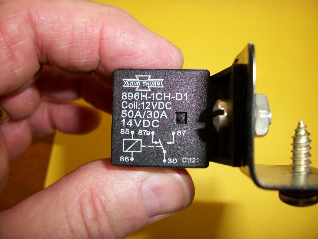
|
   |

 
|
  |
Replies
| Tom |
May 16 2012, 06:15 AM
Post
#2
|
|
Advanced Member Group: Members Posts: 2,139 Joined: 21-August 05 From: Port Orchard, WA 98367 Member No.: 4,626 Region Association: None |
As you can see from the pictures the large yellow wire needs to be removed from the 12 pin connector and insulated at that end as well as the starter end. A new 20 ga. yellow wire needs to be soldered to the pin for #6 of the 12 pin connector. The other end will need to be soldered to the anode of D1. The cathode end of D1 and a 20 ga. white wire need to be crimped/soldered or both depending on the type of female spade connector being used and this connector labeled 86. The other end of this white wire will go to either side of the push switch.
The other white wire from the [push switch will need to go into another female spade connector along with one of the large 12 ga. red wires and be labeled 30. This red wire will need to be about 5 to 5 and 1/2 feet long as it and the other large red wire goes back to the starter area. The starter end of this wire is where you need to place the inline fuse holder and on the end of the fuse holder wire you will need a ring terminal to place on the starter terminal with the battery lead. The other red wire needs a female spade connector and should be labeled 87. The other end of this wire(87) will also need a female spade connector to allow connecting to the solenoid male spade connector. The last wire is a 20 ga brown that needs to be long enough to place a ring terminal under one of the securing screws on the relay board ( ground). The diodes are there to D1- steer the push button voltage to only the relay and not back to the #6 pin of the 12 pin connector, and D2 - to suppress the inductive spike and give the relay contacts a longer life. Some parts were ordered from DELCITY and some Radio Shack or local parts houses. I carry an extra relay just in case it goes out as it may be hard to find one at inopportune times. As can be seen in the pics, I don't have a rear window defog relay. If I did, I would have had to route the wires a little differently. Also check your relay board for the metal insert to screw the hold down bolt into. Later one don't always have it. Mine did not and I made one from brass and glued it in. Before you attempt this, please have someone you trust with electrics look over the schematic and give a second opinion for you. Tom Attached thumbnail(s) 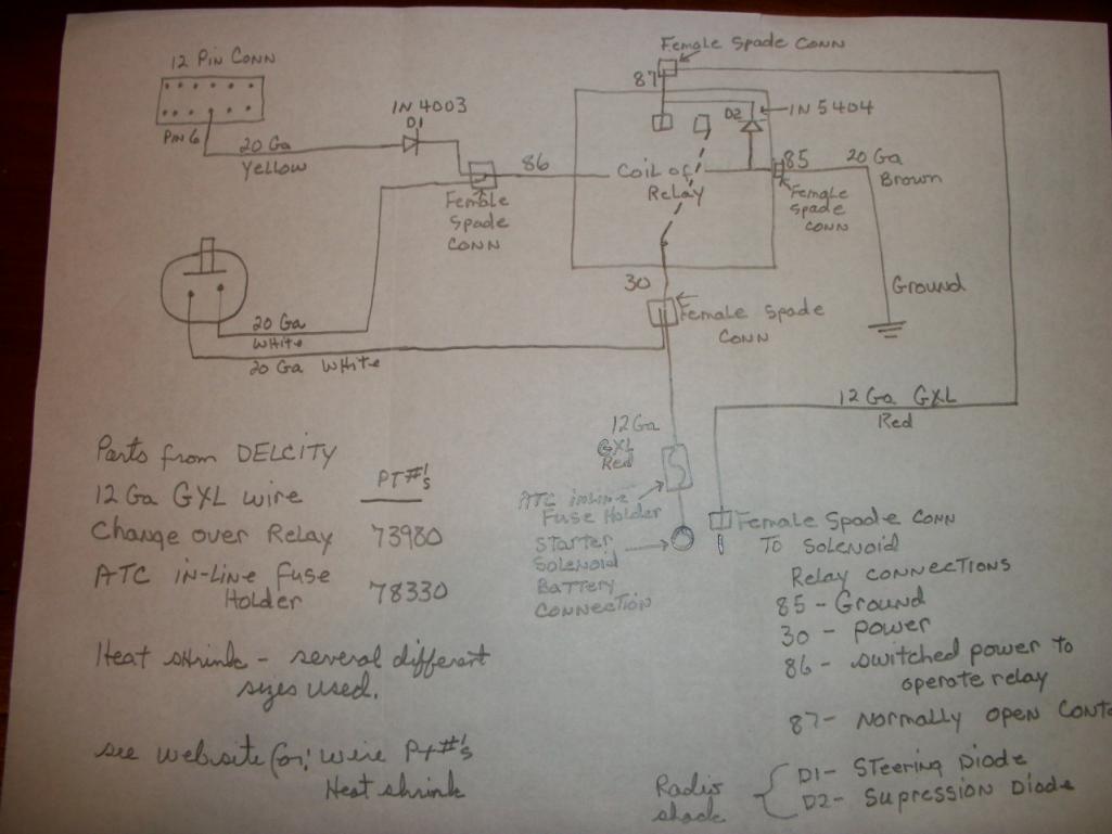
|
|
|
|
Posts in this topic
 Tom starter relay Oct 25 2011, 06:31 PM
 Tom Pics are large, so several posts will be needed. Oct 25 2011, 06:33 PM Tom another one Oct 25 2011, 06:34 PM 76-914 Very nice Tom, but I'm not taking my Ford rela... Oct 25 2011, 08:28 PM Tom 76-914,
No reason to, the Ford relay is just g... Oct 25 2011, 09:20 PM Drums66 .....Copy of the hot start kit in another location... Oct 26 2011, 05:19 PM Tom Drums,
Thanks for the compliment. :) Yea,... Oct 27 2011, 01:41 PM Tom I have been thinking of the next generation of thi... Feb 9 2012, 06:40 AM
Tom Pics are large, so several posts will be needed. Oct 25 2011, 06:33 PM Tom another one Oct 25 2011, 06:34 PM 76-914 Very nice Tom, but I'm not taking my Ford rela... Oct 25 2011, 08:28 PM Tom 76-914,
No reason to, the Ford relay is just g... Oct 25 2011, 09:20 PM Drums66 .....Copy of the hot start kit in another location... Oct 26 2011, 05:19 PM Tom Drums,
Thanks for the compliment. :) Yea,... Oct 27 2011, 01:41 PM Tom I have been thinking of the next generation of thi... Feb 9 2012, 06:40 AM Prospectfarms
I have been thinking of the next generation of th... Feb 9 2012, 07:10 AM pcar916
... add a push to start switch so when I need to ... Feb 9 2012, 08:54 AM
Prospectfarms
I have been thinking of the next generation of th... Feb 9 2012, 07:10 AM pcar916
... add a push to start switch so when I need to ... Feb 9 2012, 08:54 AM 76-914
I have been thinking of the next generation of th... Feb 9 2012, 09:17 AM vsg914 So you spent a little time and money to fix a prob... Feb 9 2012, 07:16 AM Prospectfarms :blink:
discuss starter switch problems
Hot st... Feb 9 2012, 08:15 AM Cap'n Krusty Look out Maude, here comes the rain on the parade... Feb 9 2012, 09:15 AM Elliot Cannon
Look out Maude, here comes the rain on the parade... Feb 10 2012, 10:53 AM Tom pcar916,
I haven't finalized what I will ... Feb 9 2012, 09:26 AM Tom Cap'n Krusty,
Rain away, we PNWers are used... Feb 9 2012, 09:29 AM andys My '47 Ford had a button right on the relay th... Feb 9 2012, 11:31 AM ClayPerrine We had hot start problems with both 914s, but putt... Feb 9 2012, 12:28 PM pcar916
... putting on a gear drive starter cured that on... Feb 9 2012, 12:58 PM Tom Prospectfarms,
No starter relay in the 914. T... Feb 9 2012, 02:10 PM 76-914
Prospectfarms,
I have no plans at ... Feb 10 2012, 07:24 PM Prospectfarms Yes, I understand that every time you open a circu... Feb 10 2012, 12:15 AM Tom Well, now that I have the fuse block kits all done... Apr 6 2012, 10:49 AM Tom With no forum to spend time on, I found time to fi... May 15 2012, 06:01 AM 76-914 Tom, I received my kit while this site was down. C... May 15 2012, 09:15 AM Tom Kent,
I sent you a PM. I think I put in some... May 15 2012, 01:11 PM Valy Tom very nice but a word of advise:
Please, put a ... May 15 2012, 01:20 PM jim_hoyland Like your idea, very clean installation. If the wi... May 15 2012, 04:33 PM Tom Jim,
With the key off, the coil has no power ... May 15 2012, 07:08 PM jim_hoyland Please post the schematic, the parts list, and ins... May 15 2012, 07:33 PM Tom Jim,
I'll put an updated schematic tomorrow... May 15 2012, 09:22 PM Tom Additional pics for illustration purposes.
To... May 16 2012, 06:18 AM Tom more.
Even though this is first gen of this m... May 16 2012, 06:20 AM jim_hoyland Am I correct that the relay will be used by both t... May 16 2012, 08:49 AM Tom Jim,
Yes, the relay works for both the key swit... May 16 2012, 08:58 AM jim_hoyland Just installed the relay today. How much amperage ... Jul 3 2012, 06:21 PM 76-914 Jim, the amp load to activate the relay is minimal... Jul 3 2012, 06:32 PM Tom Jim,
The relay I used draws about 145 miliAmps... Jul 4 2012, 03:12 AM Harpo Good afternoon Tom,
You posted that these kits ar... Jul 4 2012, 10:53 AM Tom Auto Atlanta sells them. They are in the catalogue... Jul 4 2012, 11:44 AM jim_hoyland Finally completed the hot start relay and added th... Jul 6 2012, 02:35 PM jim_hoyland Remote starter unit. Momentary switch and magnet..... Jul 6 2012, 02:37 PM jim_hoyland Installed out of view, and set up on grill.... Jul 6 2012, 02:38 PM Tom Jim,
That is looking nice, glad it all worked o... Jul 6 2012, 07:02 PM
76-914
I have been thinking of the next generation of th... Feb 9 2012, 09:17 AM vsg914 So you spent a little time and money to fix a prob... Feb 9 2012, 07:16 AM Prospectfarms :blink:
discuss starter switch problems
Hot st... Feb 9 2012, 08:15 AM Cap'n Krusty Look out Maude, here comes the rain on the parade... Feb 9 2012, 09:15 AM Elliot Cannon
Look out Maude, here comes the rain on the parade... Feb 10 2012, 10:53 AM Tom pcar916,
I haven't finalized what I will ... Feb 9 2012, 09:26 AM Tom Cap'n Krusty,
Rain away, we PNWers are used... Feb 9 2012, 09:29 AM andys My '47 Ford had a button right on the relay th... Feb 9 2012, 11:31 AM ClayPerrine We had hot start problems with both 914s, but putt... Feb 9 2012, 12:28 PM pcar916
... putting on a gear drive starter cured that on... Feb 9 2012, 12:58 PM Tom Prospectfarms,
No starter relay in the 914. T... Feb 9 2012, 02:10 PM 76-914
Prospectfarms,
I have no plans at ... Feb 10 2012, 07:24 PM Prospectfarms Yes, I understand that every time you open a circu... Feb 10 2012, 12:15 AM Tom Well, now that I have the fuse block kits all done... Apr 6 2012, 10:49 AM Tom With no forum to spend time on, I found time to fi... May 15 2012, 06:01 AM 76-914 Tom, I received my kit while this site was down. C... May 15 2012, 09:15 AM Tom Kent,
I sent you a PM. I think I put in some... May 15 2012, 01:11 PM Valy Tom very nice but a word of advise:
Please, put a ... May 15 2012, 01:20 PM jim_hoyland Like your idea, very clean installation. If the wi... May 15 2012, 04:33 PM Tom Jim,
With the key off, the coil has no power ... May 15 2012, 07:08 PM jim_hoyland Please post the schematic, the parts list, and ins... May 15 2012, 07:33 PM Tom Jim,
I'll put an updated schematic tomorrow... May 15 2012, 09:22 PM Tom Additional pics for illustration purposes.
To... May 16 2012, 06:18 AM Tom more.
Even though this is first gen of this m... May 16 2012, 06:20 AM jim_hoyland Am I correct that the relay will be used by both t... May 16 2012, 08:49 AM Tom Jim,
Yes, the relay works for both the key swit... May 16 2012, 08:58 AM jim_hoyland Just installed the relay today. How much amperage ... Jul 3 2012, 06:21 PM 76-914 Jim, the amp load to activate the relay is minimal... Jul 3 2012, 06:32 PM Tom Jim,
The relay I used draws about 145 miliAmps... Jul 4 2012, 03:12 AM Harpo Good afternoon Tom,
You posted that these kits ar... Jul 4 2012, 10:53 AM Tom Auto Atlanta sells them. They are in the catalogue... Jul 4 2012, 11:44 AM jim_hoyland Finally completed the hot start relay and added th... Jul 6 2012, 02:35 PM jim_hoyland Remote starter unit. Momentary switch and magnet..... Jul 6 2012, 02:37 PM jim_hoyland Installed out of view, and set up on grill.... Jul 6 2012, 02:38 PM Tom Jim,
That is looking nice, glad it all worked o... Jul 6 2012, 07:02 PM |
2 User(s) are reading this topic (2 Guests and 0 Anonymous Users)
0 Members:

|
Lo-Fi Version | Time is now: 31st May 2026 - 07:39 AM |
Invision Power Board
v9.1.4 © 2026 IPS, Inc.