|
|
|
Porsche, and the Porsche crest are registered trademarks of Dr. Ing. h.c. F. Porsche AG.
This site is not affiliated with Porsche in any way. Its only purpose is to provide an online forum for car enthusiasts. All other trademarks are property of their respective owners. |
|
|


| Tom |
 Mar 9 2012, 12:30 PM Mar 9 2012, 12:30 PM
Post
#1
|
|
Advanced Member  Group: Members Posts: 2,139 Joined: 21-August 05 From: Port Orchard, WA 98367 Member No.: 4,626 Region Association: None |
Have you checked yours lately? These seem to be becoming more of a problem. When I redid mine, I found the wires to have multiple broken strands at the solder to wire connection. As more strands are broken, the current carrying capacity of the wire is degraded. Below is something I copied from a forum on solder/crimp connections.
Almost any soldered joint will last forever if there's no vibration - that's the key. The solder itself isn't what fails, it's the interface point between the copper wire and solder, that's where the wires - not the solder - fail. How true and this is just what I found on mine. If yours are OK, a way to help prevent the breakage of the strands is to immobilize the 4 wire harness with a sticky pad and a nylon tie as close to the connection as possible. Two, one above the other would be even better. This would keep vibration and movement to a minimum. I think most of our cars used to have a small piece of thin sheet metal welded to the left rear side of the battery tray just for this purpose, however, most are long gone. From the pics of engine bays I have looked at, almost none were being used and the harness was hanging loose, allowing vibration and movement that stresses the soldered connection. If your 4 wire harness is long enough, you could do what I did in the pic attached. If you decide to do this, check how much movement you get by shaking the harness below the tie point and see how much less movement you get at the soldered connection. Tom Attached thumbnail(s) 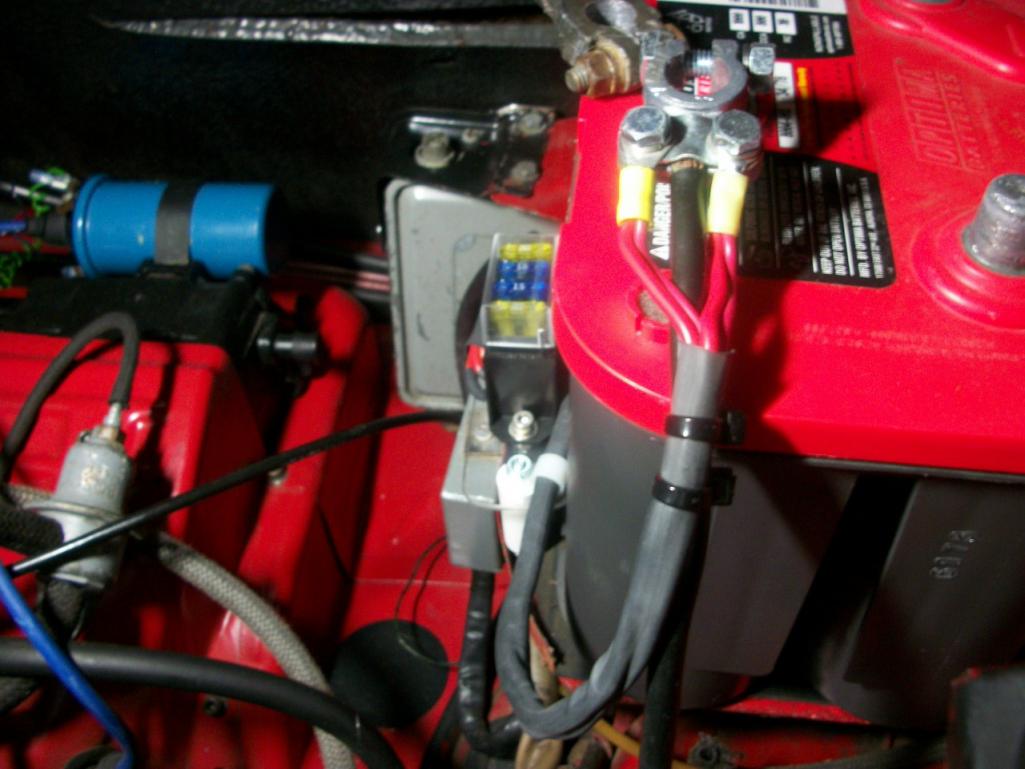
|
   |

 
|
  |
Replies
| Tom |
Sep 30 2012, 05:02 PM
Post
#2
|
|
Advanced Member Group: Members Posts: 2,139 Joined: 21-August 05 From: Port Orchard, WA 98367 Member No.: 4,626 Region Association: None |
All terminal crimps do not get two crimps. A lot of the non insulated terminals get only one. This thread is not about crimping versus solder, however, It is about the 4 red wires, or three on early cars, and how they degrate over time due to vibration.
I did an autopsy on my wires there at the battery some time back when I replaced my connectors and added the fuse block. On one of the 4.0mm wires, I had about 19 of the 55 strands broken at the solder connection. So I was in effect losing 1/3 or more of the current carrying capability on that wire. Factory connectors are soldered there. On one of the 2.5mm wires I thing half were broken. Seeing as how the youngest of our cars is 36+ years old, it would be a good idea for those wires to be closely checked, especially if you are having wierd electrical issues. Tom |
|
|
|
Posts in this topic
Tom Power wires at battery + Mar 9 2012, 12:30 PM 76-914 Along those lines; years ago when I built my plane... Mar 9 2012, 01:56 PM vsg914 Yep. The non insulated crimp spot on the tool will... Mar 9 2012, 03:50 PM Tom The type of crimpers that 76-914 is talking about ... Mar 9 2012, 05:17 PM Tom Over the last month, I have read several threads w... Sep 30 2012, 03:20 PM damesandhotrods A crimp terminal gets two crimps. The first is fo... Sep 30 2012, 03:29 PM
|
2 User(s) are reading this topic (2 Guests and 0 Anonymous Users)
0 Members:

|
Lo-Fi Version | Time is now: 7th March 2026 - 01:42 AM |
Invision Power Board
v9.1.4 © 2026 IPS, Inc.