|
|
|
Porsche, and the Porsche crest are registered trademarks of Dr. Ing. h.c. F. Porsche AG.
This site is not affiliated with Porsche in any way. Its only purpose is to provide an online forum for car enthusiasts. All other trademarks are property of their respective owners. |
|
|


| warrenoliver |
 May 25 2013, 06:01 PM May 25 2013, 06:01 PM
Post
#1
|
|
Member  Group: Members Posts: 363 Joined: 11-November 06 From: McFarland, Wisconsin Member No.: 7,199 Region Association: Upper MidWest |
I am running down a difficult fuel pump problem with my 73, 2.0 with FI. The circuit board on Brad Ander's site shows the position of the 86 and 85 pin swapped. The first image is from Ander's site. The second one is from one of our members - Tom who put in in my previous thread. Tom's pic is the same as the one that Dr. 914 has in his 700 Tech Tips book. Which one is right? Is this image as if i were viewing from the bottom so I can see the traces on the relay board? It is important for me to know since I need to know which one should have power when following Brad Ander's troubleshooting.
If i follow the print on the relay itself, it looks to me like the Ander's one is mislabled. The relay itself shows the 86 pin on the driver's side of the power relay pins and 85 being on the passenger side. I need to know if socket 86 on relay 75 has 12V when the key is on relay boards that are good. Mine does not have 12V to 86 (socket on driver's side). If other's do have power there, it looks like I may have a bad board. Can someone check theirs and let me know? 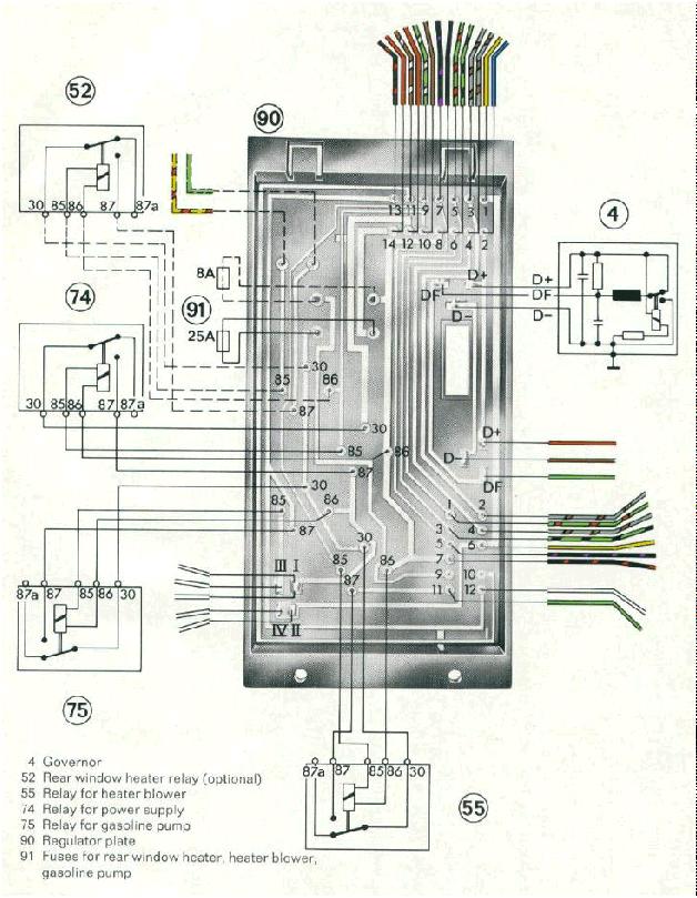 Tom and Dr. 914's drawing 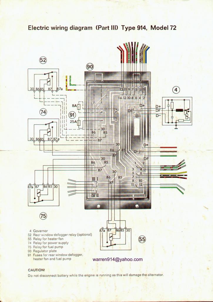 |
   |

 
|
  |
Replies
| Tom |
May 25 2013, 06:53 PM
Post
#2
|
|
Advanced Member Group: Members Posts: 2,139 Joined: 21-August 05 From: Port Orchard, WA 98367 Member No.: 4,626 Region Association: None |
Warren,
It doesn't matter what number is assigned to the position. One side is power and the other is a switched ground. The fuel pump relay socket should have power to the socket at the 3 O'clock position ( pass side), no matter if it is labeled 85 or 86. Follow it down from #87 of the power relay. When the power relay is energized, then the fuel pump relay should have power to the socket at the 3 O'clock position. When the ECU provides a ground to the 9 O'clock position ( driver's side), then the fuel pump relay is energized. If you look at the relay and the sockets, the numbers are reversed between pics for relay #75 but are electrically the same. Tom |
|
|
|
| warrenoliver |
May 25 2013, 07:05 PM
Post
#3
|
|
Member Group: Members Posts: 363 Joined: 11-November 06 From: McFarland, Wisconsin Member No.: 7,199 Region Association: Upper MidWest |
I hate electrical problems!
When I look at the diagram, what i see usually labeled as 86 and is at 7 oclock postion does not have power to the pin on the fuel pump relay - it doesn't have power during the first 1 1/2 seconds after i turn the key. I think it is supposed to have 12V when I first turn the key - unless i am chasing my tail here. |
|
|
|
Posts in this topic
warrenoliver Relay Board Image May 25 2013, 06:01 PM
 Tom Warren,
Looking at the lower of the two pics, 8... May 25 2013, 07:26 PM
Tom Warren,
Looking at the lower of the two pics, 8... May 25 2013, 07:26 PM wndsnd The factory manual shows boards for 71,72, and 73.... May 25 2013, 07:37 PM
 |
1 User(s) are reading this topic (1 Guests and 0 Anonymous Users)
0 Members:

|
Lo-Fi Version | Time is now: 9th June 2026 - 02:28 AM |
Invision Power Board
v9.1.4 © 2026 IPS, Inc.