|
|
|
Porsche, and the Porsche crest are registered trademarks of Dr. Ing. h.c. F. Porsche AG.
This site is not affiliated with Porsche in any way. Its only purpose is to provide an online forum for car enthusiasts. All other trademarks are property of their respective owners. |
|
|


| timothy_nd28 |
 Jun 10 2013, 12:27 AM Jun 10 2013, 12:27 AM
Post
#1
|
|
Advanced Member  Group: Members Posts: 2,299 Joined: 25-September 07 From: IN Member No.: 8,154 Region Association: Upper MidWest |
This is a tribute thread for the late Al Garcia, RIP
Many of us have issues with the inadequate lighting on our gauge cluster. This is a tutorial on how to increase the lighting for the DIY'er and for under 20 bucks. Euro911 was nice enough to be the guinea pig, in which he donated his gauges for this build. I rate the skill level at around a 3. 1 being easy (adding blinker fluid) and 10 (setting up valve geometry). 1st step, remove the combo/speedometer/tach from your car. Alrighty, easy enough. 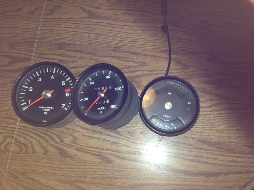 2nd step, drink a beer or two. This is somewhat unnerving and for the few it may turn you off. However, this isn't all that bad. We need to remove the bezel trim rings. I'm sure there is a machine out there that cost 15k, that will do this in about 10 seconds but we will use a small screwdriver. The first time I did this (my gauges) it took around 40 mins each, and I had a good size blister on my index finger. You will get a feeling that you are absolutely ruining these rings, but your not. Wedge the screw driver in between the bezel and the gauge can. Once your in, lightly twist back and forth the screw drive in situ pushing in a forward direction. By the time you get to the third gauge, you'll be a pro! I also found that it is unnecessary to uncrimp the entire circumference of the bezel ring. Once you get 3/4 around, the last 1/4 will pop off. 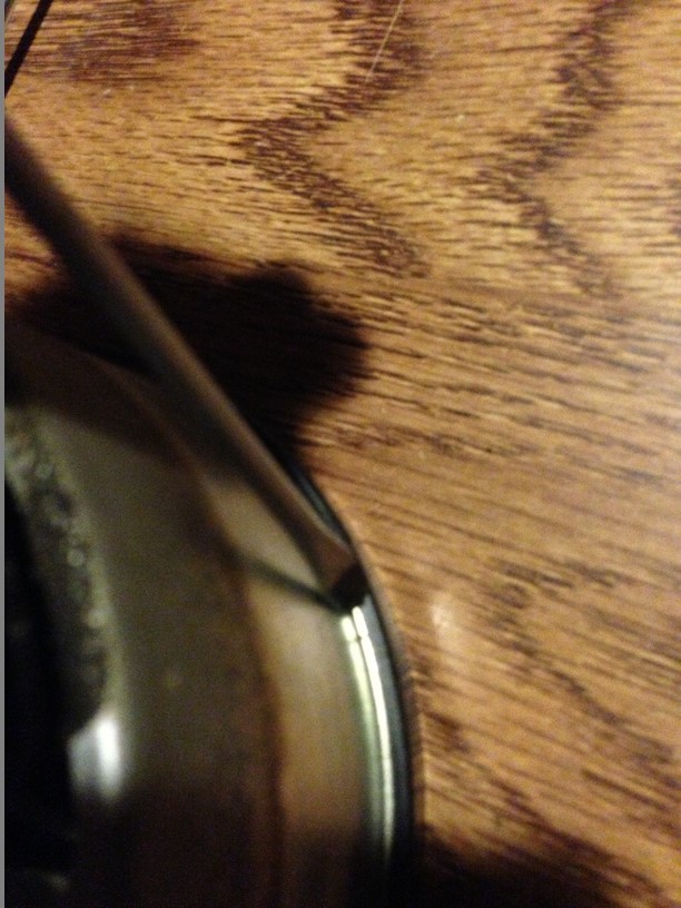 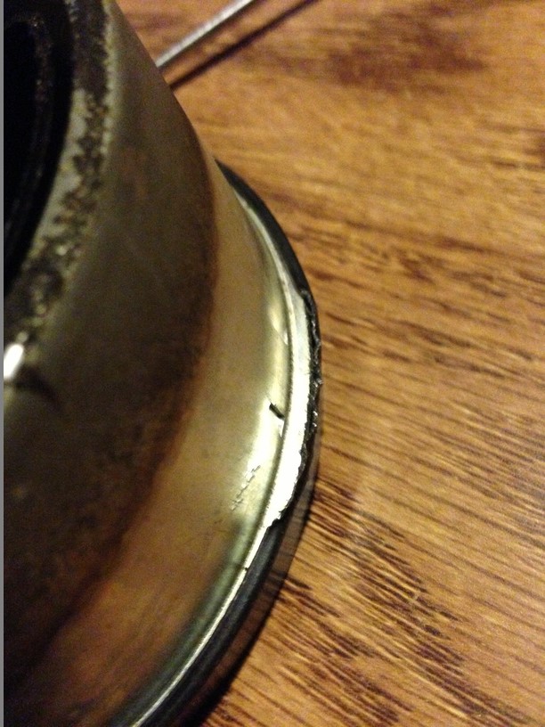 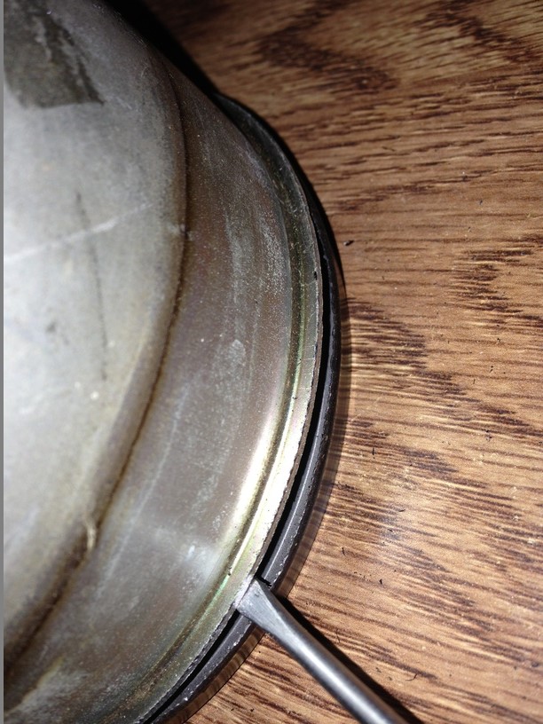 Now that these ring are off, go ahead and remove the insides. The tach will have 4 brass screws and the odometer will have 2. The combo gauge will have either 4 or 8 screws depending on the year. 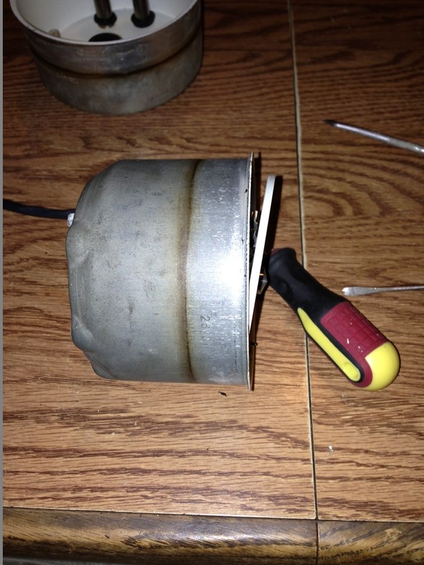 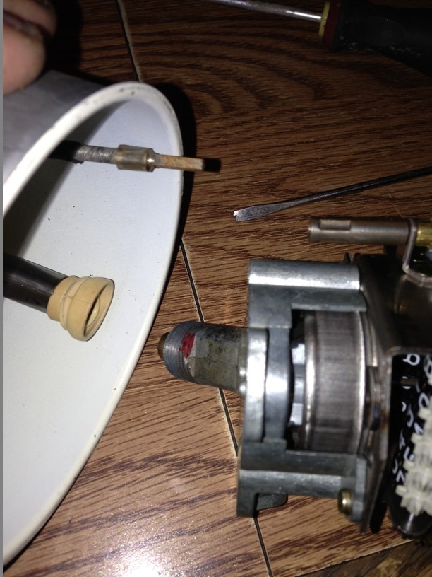 Now that the inner guts have been removed, you should have 3 empty cans like this 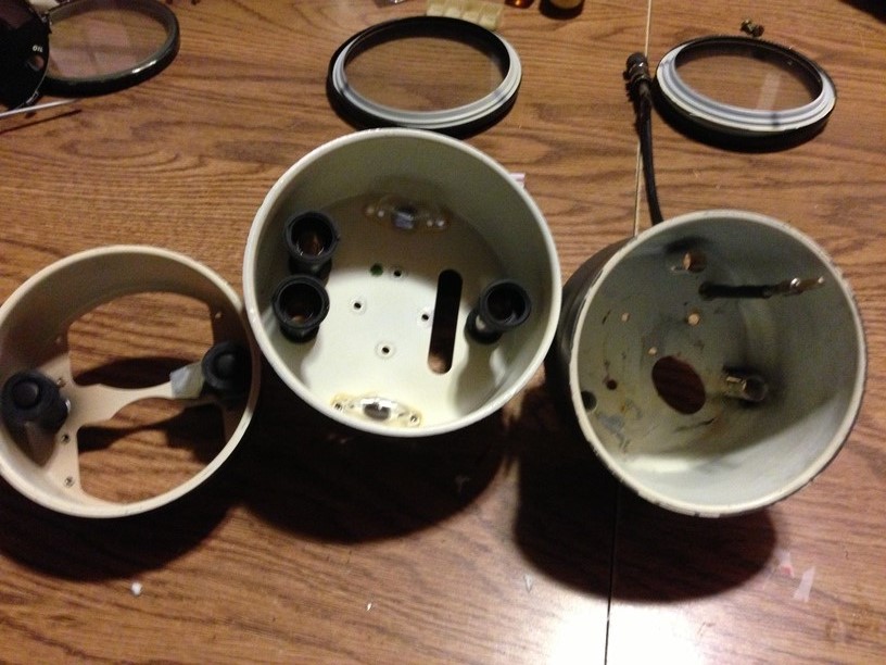 We will need to clean the inside of these cans, for the best adhesion of the LED lights in a future step. I didn't use anything special, good old windex spray should suffice. 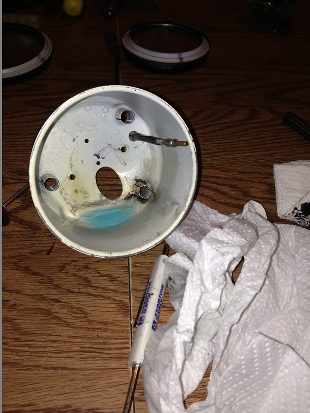 |
   |

 
|
  |
Replies
| timothy_nd28 |
Jun 10 2013, 12:28 AM
Post
#2
|
|
Advanced Member Group: Members Posts: 2,299 Joined: 25-September 07 From: IN Member No.: 8,154 Region Association: Upper MidWest |
Step 2 made me forget to take pictures of reassembly, for that I apologize. After these LED strips are installed, go ahead and reassemble each gauge. You will need to hook in the bezel ring (the small area that you didn't uncrimp) and pop in the rest. With your screw driver, carefully push down and re-crimp the bezel to the gauge can. This step is pretty straight forward.
This is what it should look like after reassembly. Notice the pretty color on the needles 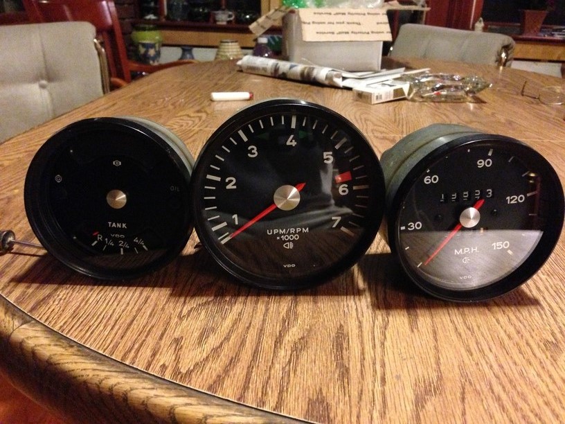 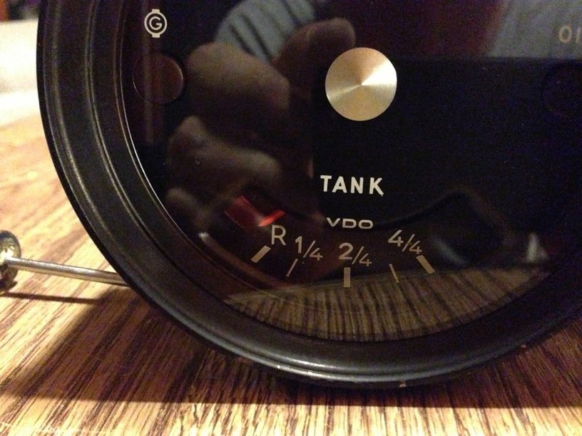 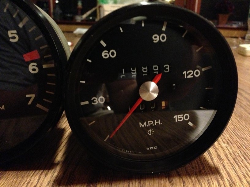 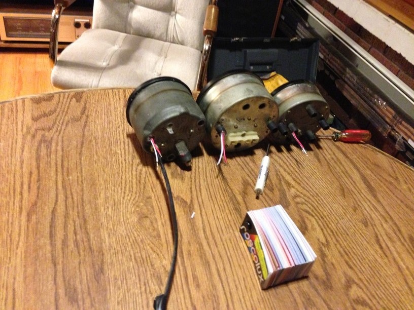 Now onto the wiring. We need to build a harness to jumper all the grounds together. You should have a brown wire that ties to the combo gauge, so we need to splice into this, without cutting wires. 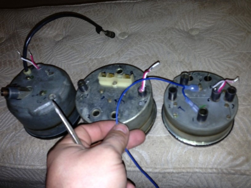 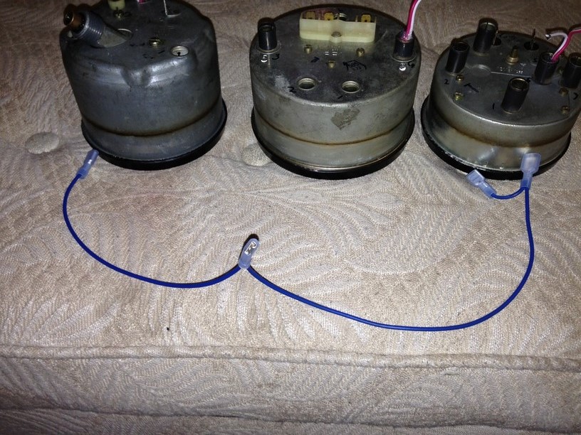 I should of used brown wire instead of blue, but this is all I had laying around. Obtain a piece of wire about 20" long or so. On one end, add a insulated 1/4" female terminal. Going from that terminal you just installed, move in about 10" and add another 1/4" female terminal. The opposite end of the wire gets abit squirrelly. We need to add 2 more female terminals and a male terminal (see picture). The male terminal will plug into the car's brown ground wire. The female on that end will plug onto the gauge where the brown used to go. This leaves you with 3 female terminals on the harness you just made that will plug into the (white) wires on the LED flex strip. White is ground on this flex strip, whereas red is positive. 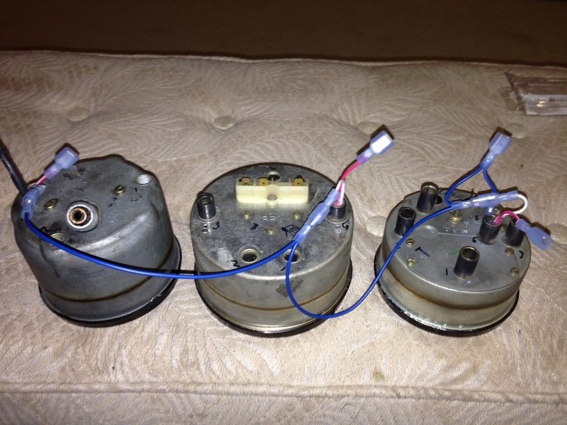 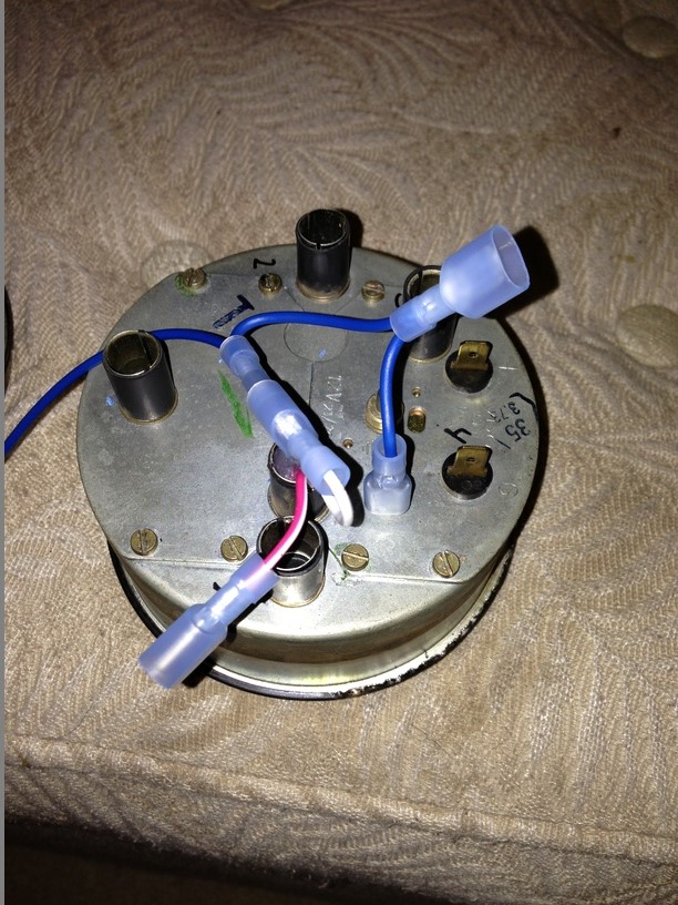 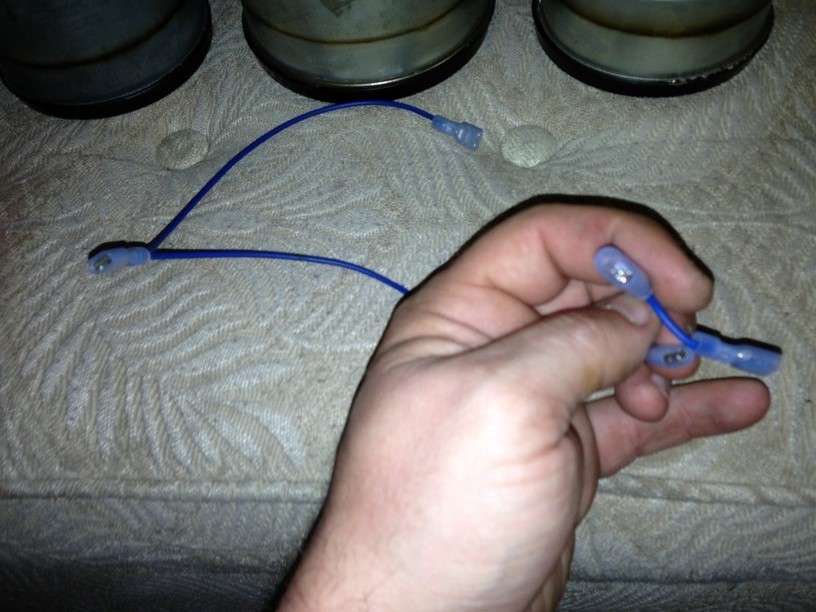 Towards the wires from the led flex strip (protruding the light tubes) you'll need to add male 1/4" insulated terminals to all the wires. This will mate with the harness you made with the car's electrical connectors. This makes for a pretty clean install. Keep in mind that the white wires are negative (ground) and the red are positive (+12vdc) Here is a diagram borrowed from Jeff Bowlsby's website to help aid with re-installation. 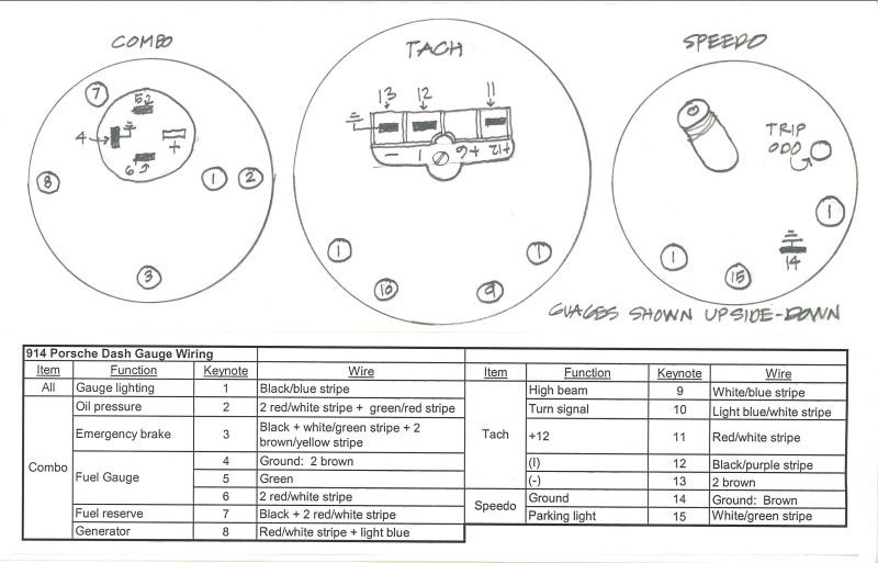 |
|
|
|
Posts in this topic
 timothy_nd28 Gauge Lighting Jun 10 2013, 12:27 AM
 timothy_nd28 Since the inside guts are out and very accessible,... Jun 10 2013, 12:27 AM timothy_nd28 Towards the LED's, there is a plethora of styl... Jun 10 2013, 12:28 AM timothy_nd28 Here is the finished product. The camera made the... Jun 10 2013, 12:29 AM r3dplanet :popcorn: Jun 10 2013, 12:38 AM bulitt :beer2: Thx for posting this! Jun 10 2013, 01:54 AM Chris H. Amazing work Tim! Thank you for the very deta... Jun 10 2013, 08:59 AM 76-914 Al would be proud of you. :poke: Now throw those... Jun 10 2013, 09:20 AM ellisor3 Great Tribute Thread. Al was a great guy, helped ... Jun 10 2013, 09:34 AM mrholland2 While my car is down, I would love to see the mult... Jun 10 2013, 10:22 AM mrholland2 Oh, and are there LED instructions for the blinker... Jun 10 2013, 10:27 AM
 timothy_nd28
Oh, and are there LED instructions for the blinke... Jun 10 2013, 10:33 PM pcar916
The catch is finding a controller that turns on t... Jun 11 2013, 05:47 AM Spoke Good write up.
Put this in the Classics Forum. Jun 10 2013, 10:36 AM turk22 very nice write up!
Still scares the shat out... Jun 10 2013, 12:55 PM poorsche914 Thanks for the write up. I have been planning to r... Jun 10 2013, 03:51 PM euro911 Wow. No, I mean WOW!
I really didn't know... Jun 11 2013, 02:13 AM Steve Thank you very much for posting this!!
I j... Jun 11 2013, 11:53 AM Madswede This is a shoo-in for the "Classic" foru... Jun 11 2013, 01:53 PM SUNAB914 Man, that is nice and I sold my cars/parts to Bill... Jun 11 2013, 02:00 PM Mr.242
This is a tribute thread for the late Al Garcia, ... Jun 12 2013, 09:47 AM timothy_nd28 Hey guys I have an idea for the next build. Same ... Jun 12 2013, 01:36 PM bperry I re-did my '74 gauges (tach and speedo) back ... Jun 12 2013, 11:15 PM bandjoey Does it help to paint the can inside? White? Sil... Jun 12 2013, 11:47 PM timothy_nd28
Does it help to paint the can inside? White? Si... Dec 4 2013, 06:59 PM Rob-O :agree:
I measured the glass and it seems to be ... Jun 13 2013, 08:14 AM Rob-O Oh, three other points. When I restored mine (min... Jun 13 2013, 08:21 AM timothy_nd28 :bump: This thread corresponds to my near future ... Jul 2 2013, 02:40 PM scotty b
:bump: This thread corresponds to my near future... Jul 2 2013, 05:50 PM gothspeed Simply amazing!!!! :trophy:
Thank... Dec 5 2013, 08:50 AM PThompson509
Oh, and are there LED instructions for the blinke... Dec 9 2013, 10:08 PM john77 Finally got all the parts to start this great DIY ... Feb 12 2015, 08:32 PM euro911 ... and almost 2 years since Tim upgraded a set of... Mar 5 2015, 12:25 AM Cuda911 Great work!!!
Regarding replacing the... Mar 5 2015, 02:44 AM euro911 I swapped out most of the incandescent bulbs with ... Mar 5 2015, 08:41 PM rnellums I'm really pumped. My Next-Gen LED gauges are ... Mar 5 2015, 08:45 PM
timothy_nd28
Oh, and are there LED instructions for the blinke... Jun 10 2013, 10:33 PM pcar916
The catch is finding a controller that turns on t... Jun 11 2013, 05:47 AM Spoke Good write up.
Put this in the Classics Forum. Jun 10 2013, 10:36 AM turk22 very nice write up!
Still scares the shat out... Jun 10 2013, 12:55 PM poorsche914 Thanks for the write up. I have been planning to r... Jun 10 2013, 03:51 PM euro911 Wow. No, I mean WOW!
I really didn't know... Jun 11 2013, 02:13 AM Steve Thank you very much for posting this!!
I j... Jun 11 2013, 11:53 AM Madswede This is a shoo-in for the "Classic" foru... Jun 11 2013, 01:53 PM SUNAB914 Man, that is nice and I sold my cars/parts to Bill... Jun 11 2013, 02:00 PM Mr.242
This is a tribute thread for the late Al Garcia, ... Jun 12 2013, 09:47 AM timothy_nd28 Hey guys I have an idea for the next build. Same ... Jun 12 2013, 01:36 PM bperry I re-did my '74 gauges (tach and speedo) back ... Jun 12 2013, 11:15 PM bandjoey Does it help to paint the can inside? White? Sil... Jun 12 2013, 11:47 PM timothy_nd28
Does it help to paint the can inside? White? Si... Dec 4 2013, 06:59 PM Rob-O :agree:
I measured the glass and it seems to be ... Jun 13 2013, 08:14 AM Rob-O Oh, three other points. When I restored mine (min... Jun 13 2013, 08:21 AM timothy_nd28 :bump: This thread corresponds to my near future ... Jul 2 2013, 02:40 PM scotty b
:bump: This thread corresponds to my near future... Jul 2 2013, 05:50 PM gothspeed Simply amazing!!!! :trophy:
Thank... Dec 5 2013, 08:50 AM PThompson509
Oh, and are there LED instructions for the blinke... Dec 9 2013, 10:08 PM john77 Finally got all the parts to start this great DIY ... Feb 12 2015, 08:32 PM euro911 ... and almost 2 years since Tim upgraded a set of... Mar 5 2015, 12:25 AM Cuda911 Great work!!!
Regarding replacing the... Mar 5 2015, 02:44 AM euro911 I swapped out most of the incandescent bulbs with ... Mar 5 2015, 08:41 PM rnellums I'm really pumped. My Next-Gen LED gauges are ... Mar 5 2015, 08:45 PM |
2 User(s) are reading this topic (2 Guests and 0 Anonymous Users)
0 Members:

|
Lo-Fi Version | Time is now: 1st August 2026 - 05:05 AM |
Invision Power Board
v9.1.4 © 2026 IPS, Inc.