|
|
|
Porsche, and the Porsche crest are registered trademarks of Dr. Ing. h.c. F. Porsche AG.
This site is not affiliated with Porsche in any way. Its only purpose is to provide an online forum for car enthusiasts. All other trademarks are property of their respective owners. |
|
|


| malcolm2 |
 Oct 14 2014, 09:00 PM Oct 14 2014, 09:00 PM
Post
#1
|
|
Advanced Member  Group: Members Posts: 2,745 Joined: 31-May 11 From: Nashville Member No.: 13,139 Region Association: South East States |
I have had this gauge for a while. I also found the complete taco plate, sender etc... to set it up. I decided to test it. I tested the sender a while back in hot water and remember getting various readings as the temp increased.
I pulled out my 12v powered drill battery, put 12v + on the + terminal of the gauge and the - on the - of the gauge. ( you can't see the - wire in the picture, but it is there) The gauge moved to where it is in the picture without the sender even being connected. It did not move once the sender was connected. Inside the temp gauge are the following #s. Far left 30, at the start of the red line 156.7 and the end of the red line 170 *C The top of the paper is what is stamped on each face of the hex and the gauge part # has been edited to what you see in the picture. 1. why is the gauge moving at room temp with or with out the sender? 2. do I have this thing hooked up right? any alternate testing suggestions? 3. do I have a matched sender & gauge? 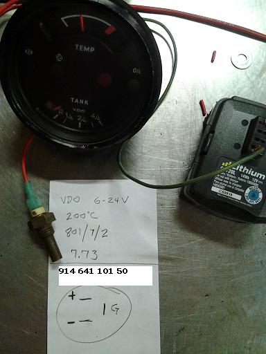 |
   |

 
|
  |
Replies
| timothy_nd28 |
Oct 20 2014, 10:04 PM
Post
#2
|
|
Advanced Member Group: Members Posts: 2,299 Joined: 25-September 07 From: IN Member No.: 8,154 Region Association: Upper MidWest |
You should test the potentiometer first. Measure the total resistance of the pot by checking the outer terminals, it should measure 1k (1000) ohms.
If this checks out fine, then put one meter lead to the middle pin, and the other meter lead on one of the 2 remaining pins (you choose). The pin that is not used, go ahead and bend it over so you don't get confused with it later. With the multimeter still on the resistance setting, observe what it is reading. Then turn the potentiometer fully in one direction, it will either read zero or 1000 ohms. Go ahead and turn it so it reads 0 ohms,,essentially a shorted state. If all of the above checks out, and the potentiometer is calibrated to 0 ohms, continue to the next step. As in post number 18, set it up the same exact way. The sensor casing is ground, and should share the same ground as the gauge ground and battery ground. The terminal on the sensor should be wired straight to the G terminal. Go ahead and boil a pot of water and verify everything still works as it did in post 18. If all checks out and works like it did earlier, then wire in the potentiometer. The terminal from the sensor needs to be wired to the middle pin on the pot. The other pin of the potentiometer needs a wire going to the G terminal on the gauge. With your multimeter, measure the resistance from the G terminal on the gauge to the terminal on the sensor. You should read 0 ohms. Now boil some water, and insert your sensor into this bath of water. Be sure that the sensor doesn't touch the sides or bottom of this boiling pot of water. You gauge should still reach the same red mark as you showed us in post #18. Now, adjust the potentiometer, by adding resistance, you should see the needle back off from the red mark. |
|
|
|
Posts in this topic
 malcolm2 oil temp combo gauge bench testing Oct 14 2014, 09:00 PM
 bdstone914
I have had this gauge for a while. I also found ... Oct 14 2014, 09:10 PM malcolm2 I have tried this set up on the car's battery ... Oct 14 2014, 09:34 PM malcolm2 morning :bump:
Anyone know what is happening her... Oct 15 2014, 05:32 AM bdstone914 Sounds like the gauge may be faulty. Did you try g... Oct 15 2014, 06:47 AM
bdstone914
I have had this gauge for a while. I also found ... Oct 14 2014, 09:10 PM malcolm2 I have tried this set up on the car's battery ... Oct 14 2014, 09:34 PM malcolm2 morning :bump:
Anyone know what is happening her... Oct 15 2014, 05:32 AM bdstone914 Sounds like the gauge may be faulty. Did you try g... Oct 15 2014, 06:47 AM
 malcolm2
Sounds like the gauge may be faulty. Did you try ... Oct 15 2014, 06:53 AM stugray
Sounds like the gauge may be faulty. Did you try... Oct 15 2014, 08:11 AM bdstone914
[quote name='malcolm2' post='2097994' date='Oct 1... Oct 15 2014, 08:41 AM malcolm2
Ground the terminal from the gauge directly. Tha... Oct 15 2014, 09:40 AM bdstone914 With either battery just jump from the G to - on t... Oct 15 2014, 09:57 AM malcolm2
[b][i]The gauge is responding to a signal when th... Oct 15 2014, 11:47 AM StratPlayer So if the gauge pegs that means the gauge is good ... Oct 15 2014, 11:26 AM timothy_nd28 For this gauge to act correctly, all wires need to... Oct 15 2014, 11:37 AM timothy_nd28 Closer look of the guts:
Oct 15 2014, 11:54 AM malcolm2
Closer look of the guts:
I just took it out, I... Oct 15 2014, 12:21 PM Dave_Darling Just to make sure:
You know that the "G... Oct 15 2014, 01:30 PM malcolm2
Just to make sure:
You know that the "G... Oct 15 2014, 05:18 PM malcolm2 :beer2:
I need to thank everyone for their help ... Oct 15 2014, 06:26 PM timothy_nd28 I'm not sure where the needle should point at ... Oct 15 2014, 06:43 PM malcolm2
I'm not sure where the needle should point at... Oct 20 2014, 09:15 PM Mblizzard Anyone figure out Clark is an engineer?
I know so... Oct 15 2014, 07:44 PM malcolm2
Anyone figure out Clark is an engineer?
I know s... Oct 16 2014, 06:29 AM malcolm2
You should test the potentiometer first. Measure... Oct 21 2014, 07:07 AM timothy_nd28 I just did a quick Google search and it looks like... Oct 20 2014, 10:19 PM timothy_nd28 The boiling water is key for this setup. The pote... Oct 21 2014, 12:05 PM malcolm2
If the sensor is at room temp, the needle is alr... Oct 21 2014, 12:46 PM ClayPerrine Has anyone noticed that there is no ground return ... Oct 21 2014, 12:56 PM malcolm2
Has anyone noticed that there is no ground return... Oct 21 2014, 01:10 PM malcolm2 Tim, you need an award. :headbanger: :headbange... Oct 21 2014, 06:10 PM timothy_nd28 A couple of things:
You can't measure resista... Oct 21 2014, 06:36 PM malcolm2
A couple of things:
You can't measure resist... Oct 21 2014, 07:07 PM stugray This is about all you ever need on this topic:
ht... Oct 21 2014, 07:08 PM malcolm2
This is about all you ever need on this topic:
h... Oct 21 2014, 07:18 PM timothy_nd28 what is the resistance of the sensor when at room ... Oct 21 2014, 07:15 PM malcolm2
what is the resistance of the sensor when at room... Oct 21 2014, 07:26 PM stugray
what is the resistance of the sensor when at room... Oct 22 2014, 12:11 AM malcolm2
So I am not quite grasping what inserting a seri... Oct 22 2014, 11:54 AM malcolm2
This post is on hold for a while. I am getting... Nov 24 2014, 07:18 PM timothy_nd28 Sorry, was unaware that the needle was not traveli... Oct 21 2014, 07:51 PM malcolm2
Sorry, was unaware that the needle was not travel... Oct 21 2014, 08:10 PM
malcolm2
Sounds like the gauge may be faulty. Did you try ... Oct 15 2014, 06:53 AM stugray
Sounds like the gauge may be faulty. Did you try... Oct 15 2014, 08:11 AM bdstone914
[quote name='malcolm2' post='2097994' date='Oct 1... Oct 15 2014, 08:41 AM malcolm2
Ground the terminal from the gauge directly. Tha... Oct 15 2014, 09:40 AM bdstone914 With either battery just jump from the G to - on t... Oct 15 2014, 09:57 AM malcolm2
[b][i]The gauge is responding to a signal when th... Oct 15 2014, 11:47 AM StratPlayer So if the gauge pegs that means the gauge is good ... Oct 15 2014, 11:26 AM timothy_nd28 For this gauge to act correctly, all wires need to... Oct 15 2014, 11:37 AM timothy_nd28 Closer look of the guts:
Oct 15 2014, 11:54 AM malcolm2
Closer look of the guts:
I just took it out, I... Oct 15 2014, 12:21 PM Dave_Darling Just to make sure:
You know that the "G... Oct 15 2014, 01:30 PM malcolm2
Just to make sure:
You know that the "G... Oct 15 2014, 05:18 PM malcolm2 :beer2:
I need to thank everyone for their help ... Oct 15 2014, 06:26 PM timothy_nd28 I'm not sure where the needle should point at ... Oct 15 2014, 06:43 PM malcolm2
I'm not sure where the needle should point at... Oct 20 2014, 09:15 PM Mblizzard Anyone figure out Clark is an engineer?
I know so... Oct 15 2014, 07:44 PM malcolm2
Anyone figure out Clark is an engineer?
I know s... Oct 16 2014, 06:29 AM malcolm2
You should test the potentiometer first. Measure... Oct 21 2014, 07:07 AM timothy_nd28 I just did a quick Google search and it looks like... Oct 20 2014, 10:19 PM timothy_nd28 The boiling water is key for this setup. The pote... Oct 21 2014, 12:05 PM malcolm2
If the sensor is at room temp, the needle is alr... Oct 21 2014, 12:46 PM ClayPerrine Has anyone noticed that there is no ground return ... Oct 21 2014, 12:56 PM malcolm2
Has anyone noticed that there is no ground return... Oct 21 2014, 01:10 PM malcolm2 Tim, you need an award. :headbanger: :headbange... Oct 21 2014, 06:10 PM timothy_nd28 A couple of things:
You can't measure resista... Oct 21 2014, 06:36 PM malcolm2
A couple of things:
You can't measure resist... Oct 21 2014, 07:07 PM stugray This is about all you ever need on this topic:
ht... Oct 21 2014, 07:08 PM malcolm2
This is about all you ever need on this topic:
h... Oct 21 2014, 07:18 PM timothy_nd28 what is the resistance of the sensor when at room ... Oct 21 2014, 07:15 PM malcolm2
what is the resistance of the sensor when at room... Oct 21 2014, 07:26 PM stugray
what is the resistance of the sensor when at room... Oct 22 2014, 12:11 AM malcolm2
So I am not quite grasping what inserting a seri... Oct 22 2014, 11:54 AM malcolm2
This post is on hold for a while. I am getting... Nov 24 2014, 07:18 PM timothy_nd28 Sorry, was unaware that the needle was not traveli... Oct 21 2014, 07:51 PM malcolm2
Sorry, was unaware that the needle was not travel... Oct 21 2014, 08:10 PM |
1 User(s) are reading this topic (1 Guests and 0 Anonymous Users)
0 Members:

|
Lo-Fi Version | Time is now: 1st June 2024 - 03:30 PM |
Invision Power Board
v9.1.4 © 2024 IPS, Inc.