|
|
|
Porsche, and the Porsche crest are registered trademarks of Dr. Ing. h.c. F. Porsche AG.
This site is not affiliated with Porsche in any way. Its only purpose is to provide an online forum for car enthusiasts. All other trademarks are property of their respective owners. |
|
|


| jim_hoyland |
 Dec 12 2015, 09:14 PM Dec 12 2015, 09:14 PM
Post
#1
|
|
Get that VIN ?  Group: Members Posts: 9,805 Joined: 1-May 03 From: Sunset Beach, CA Member No.: 643 Region Association: Southern California |
Does the turn signal switch work by completing a ground circuit or does voltage pass through it ?
|
   |

 
|
  |
Replies
| arkitect |
Dec 13 2015, 05:21 AM
Post
#2
|
|
Senior Member Group: Members Posts: 617 Joined: 3-March 10 From: Stockton, CA Member No.: 11,426 Region Association: None |
QUOTE(bulitt @ Dec 13 2015, 01:49 AM)  This is the best description of the circuit I have seen...as follows for later models 74 to 76. Dave "Hi Folks, well I'm back at it. I will go through this in 3 posts, maybe 4, so bear with me. Sorry if everyone already knew all this, but it was an epiphany for me, so maybe someone else didn't know some piece of this. First, it's important to know how the flasher itself works. There's a schematic below. There are three parts of the flasher. The primary relay (I'll call it) switches on and off and provides an on/off voltage to ANYTHING connected to it. This is controlled by the second part, a solid state timing circuit. When a load is detected, the timing circuit starts pumping out a little square wave to the coil of the primary relay, causing it to turn on and off.... By doing it this way, the frequency of the on-and-off is independent of the load, because the load on the timing circuit (ie, the relay coil) is always the same. Now it gets interesting. Notice that the output of the primary relay actually passes in series THROUGH the coil of the secondary relay. This coil is a special kind of coil that is normally used in magnetic circuit breakers rather than relays. It is a CURRENT COIL, and the secondary relay will close only when enough CURRENT is passing through it. Relays generally have voltage coils that close when the correct minimum voltage is applied. The current coil is designed to minimize voltage drop, so it is only a few turns of relatively heavy gauge wire. After it has passed through the coil of the secondary relay, it exits the flasher to be used for anything in the car that needs to flash- directional signals, hazard warning, emergency brake light, or (at least in my car) the fasten seatbelt light. The secondary relay will create a second flashing output, but only if enough current is passing through the primary flashing relay. The threshold current that trips the secondary coil will cause a secondary flashing output when the turn signals or the hazard flashers are engaged, but not when the emergency brake light or the fasten seatbelt light is engaged. They still flash because they are attached to the primary relay, which is oblivious to load, but their load isn't enough to cause the secondary output to flash. Why bother? Well, the law required a cockpit-visible indication of a burned out direction signal bulb. So if you turn on your left signal and the front bulb, say, is burned out, the rear signal will still flash, but there will be no secondary flashing output. And, you guessed it, the secondary flashing output goes to the indicator light on the dash. You can actually hear it if you sit in your car with the engine off, but turn the ignition on. Pull up on the emergency brake and listen, and then turn on one of the direction signals. The click gets audibly louder because both relays are clicking instead of just the one. I drew the '73.5-'76 circuit first, because it's easier to figure out. This secondary flashing output goes directly to the only turn signal indicator in the tach (via the blue/white wire). The other side of that indicator is grounded..... So, the driver-visible indication of a burned out bulb is- when the turn signal indicator works fine for one direction, but remains dark when you switch to signal for the other direction.... There is a bulb burned out on the latter side. Or something else that can reduce the current flow below what is required to trip the secondary relay... Like corroded contacts, corroded socket, wrong type bulb (not bright enough), bulbs replaced with LEDs, whatever that reduced the current below the flashing threshold. Next post- '70-'73.5. Somebody was on drugs when they figured that one out!" 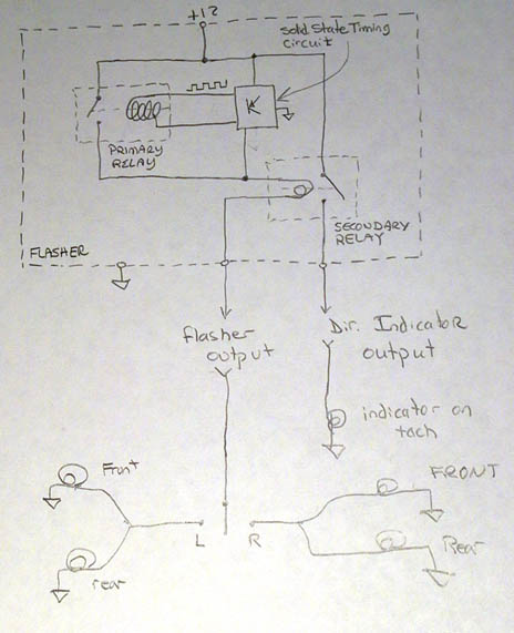 |
 |
|
Posts in this topic
 jim_hoyland Turn Signal Wires Dec 12 2015, 09:14 PM
 Dave_Darling Even if it is in the ground path, voltage still pa... Dec 12 2015, 09:51 PM Spoke The turnsignal switch and hazard switch are betwee... Dec 13 2015, 02:12 AM bulitt This may help describe the logic.
http://www.914c... Dec 13 2015, 03:49 AM arkitect Here for ease is the second description of early c... Dec 13 2015, 05:27 AM jim_hoyland Thanks for those; I forgot that back in 2006 I had... Dec 13 2015, 06:44 AM
Dave_Darling Even if it is in the ground path, voltage still pa... Dec 12 2015, 09:51 PM Spoke The turnsignal switch and hazard switch are betwee... Dec 13 2015, 02:12 AM bulitt This may help describe the logic.
http://www.914c... Dec 13 2015, 03:49 AM arkitect Here for ease is the second description of early c... Dec 13 2015, 05:27 AM jim_hoyland Thanks for those; I forgot that back in 2006 I had... Dec 13 2015, 06:44 AM
 Spoke
My follow up question: Does the early 911 wiring ... Dec 13 2015, 08:48 AM jim_hoyland Reason I asked is I may do the 911 conversion with... Dec 13 2015, 09:17 AM jim_hoyland Here is a diagram of the late connector. I could l... Dec 13 2015, 04:58 PM Dave_Darling #3: I'm not seeing gray or white at the switch... Dec 14 2015, 10:38 AM jim_hoyland Thanks Dave. I traced the gray wire back to the ig... Dec 14 2015, 11:47 AM 914Mike
Thanks Dave. I traced the gray wire back to the i... Dec 14 2015, 10:40 PM Jeff Bowlsby Jim,
3 = power to the parking lights
4 = power to... Dec 15 2015, 12:30 AM
Spoke
My follow up question: Does the early 911 wiring ... Dec 13 2015, 08:48 AM jim_hoyland Reason I asked is I may do the 911 conversion with... Dec 13 2015, 09:17 AM jim_hoyland Here is a diagram of the late connector. I could l... Dec 13 2015, 04:58 PM Dave_Darling #3: I'm not seeing gray or white at the switch... Dec 14 2015, 10:38 AM jim_hoyland Thanks Dave. I traced the gray wire back to the ig... Dec 14 2015, 11:47 AM 914Mike
Thanks Dave. I traced the gray wire back to the i... Dec 14 2015, 10:40 PM Jeff Bowlsby Jim,
3 = power to the parking lights
4 = power to... Dec 15 2015, 12:30 AM |
1 User(s) are reading this topic (1 Guests and 0 Anonymous Users)
0 Members:

|
Lo-Fi Version | Time is now: 1st July 2025 - 02:13 PM |
Invision Power Board
v9.1.4 © 2025 IPS, Inc.