|
|
|
Porsche, and the Porsche crest are registered trademarks of Dr. Ing. h.c. F. Porsche AG.
This site is not affiliated with Porsche in any way. Its only purpose is to provide an online forum for car enthusiasts. All other trademarks are property of their respective owners. |
|
|


| SKL1 |
 Feb 6 2019, 04:57 PM Feb 6 2019, 04:57 PM
Post
#1
|
|
Senior Member  Group: Members Posts: 1,778 Joined: 19-February 11 From: north Scottsdale Member No.: 12,732 Region Association: Upper MidWest |
Trying to find previous threads or info on how to add resistance to circuits after LED bulb installation. (search function not helping...)
Having issues with turn signals after changing to all LED bulbs. TIA. |
   |

 
|
  |
Replies
| Spoke |
Feb 6 2019, 07:32 PM
Post
#2
|
|
Jerry Group: Members Posts: 7,370 Joined: 29-October 04 From: Allentown, PA Member No.: 3,031 Region Association: None |
Stuart,
What issues are you seeing? With your '71 or '73, both will have separate L and R indicators in the tach. With LED turnsignals being a very light load, the common connection for the L & R indicators doesn't close and thus both L and R indicators flash together the the opposite side LEDs may flash gently. The elegant solution is to replace the OEM flasher with an LED-compatible EP26 flasher with K/C2 pin grounded internally. This is what I sell. You can add high power 6 ohm, 50W resistors to satisfy the OEM flasher. Pigtail assemblies can be found online. There are 2 issues with this: 1) you have to crimp the assembly on the wiring and the resistor has to go somewhere. 2) The lower power LEDs ease the loading on the 914 wiring. The ballast resistor simply burns power and erases the power savings on the electrical system. Here's how the 914 OEM flasher works. When the exterior bulbs are flashing and heavy current is flowing, the secondary relay connected to the K lead closes and lights just one of the tach indicators as shown by the arrows. Notice the L indicator is connected to the right turnsignals and R indicator connected to the left turnsignals. This is proper operation. 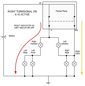 When the exterior bulbs are converted to LEDs as shown below on the left, the LEDs on the right side light up but the current is now small. So small is the current that the secondary K relay doesn't close. Thus the R and L indicators are basically in series and both flash together. This situation also occurs with standard bulbs when the efficiency of the secondary K relay drops and both flash together. With LED turnsignals, what also can happen is the current of the R and L indicators flows through the LEFT turnsignals. If all left turnsignals are LEDs, they will light up slightly. This is called ghosting. An LED will light up even with a tiny amount of current. To remedy this ghosting, the circuit on the right has the OEM flasher replaced by an LED-compatible EP26 flasher with the C2/K lead connected to ground. Now the left and right turnsignals are completely isolated from each other and no ghosting occurs. However, the R indicator will flash with the left turnsignals and L indicator with the right turnsignals. This can be fixed by pulling out the tach and swapping the entire bulb assemblies. Do not pull the wires off to swap. 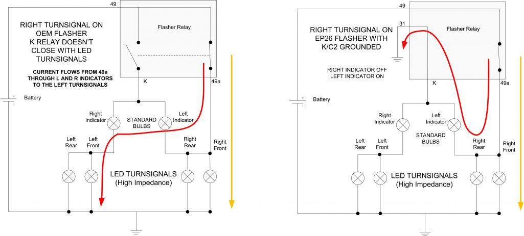 |
 |
|
Posts in this topic
 SKL1 Adding resistance after LED bulbs Feb 6 2019, 04:57 PM
 windforfun
Trying to find previous threads or info on how to... Feb 6 2019, 05:10 PM ConeDodger Spoke’s site lists a resistor for that. Feb 6 2019, 05:31 PM lierofox If your issue is hyper-flashing, and your question... Feb 6 2019, 06:06 PM
windforfun
Trying to find previous threads or info on how to... Feb 6 2019, 05:10 PM ConeDodger Spoke’s site lists a resistor for that. Feb 6 2019, 05:31 PM lierofox If your issue is hyper-flashing, and your question... Feb 6 2019, 06:06 PM
 windforfun
If your issue is hyper-flashing, and your questio... Feb 6 2019, 06:29 PM Jonathan Livesay
Trying to find previous threads or info on how to... Feb 6 2019, 07:38 PM SKL1 Thanks for the info guys- this site is always gre... Feb 6 2019, 11:08 PM Matty900 Just resolved this issue on my car. The lights cou... Feb 7 2019, 01:05 AM
windforfun
If your issue is hyper-flashing, and your questio... Feb 6 2019, 06:29 PM Jonathan Livesay
Trying to find previous threads or info on how to... Feb 6 2019, 07:38 PM SKL1 Thanks for the info guys- this site is always gre... Feb 6 2019, 11:08 PM Matty900 Just resolved this issue on my car. The lights cou... Feb 7 2019, 01:05 AM |
1 User(s) are reading this topic (1 Guests and 0 Anonymous Users)
0 Members:

|
Lo-Fi Version | Time is now: 2nd April 2026 - 01:45 PM |
Invision Power Board
v9.1.4 © 2026 IPS, Inc.