|
|
|
Porsche, and the Porsche crest are registered trademarks of Dr. Ing. h.c. F. Porsche AG.
This site is not affiliated with Porsche in any way. Its only purpose is to provide an online forum for car enthusiasts. All other trademarks are property of their respective owners. |
|
|


| johnorm |
 Jan 20 2020, 07:56 PM Jan 20 2020, 07:56 PM
Post
#1
|
|
Newbie  Group: Members Posts: 26 Joined: 28-October 18 From: Canada Member No.: 22,610 Region Association: Canada |
Guys I have an issue that I could use some help on. I'm rebuilding my 1973 914-4 wiring harness using AWG GXL wire. I have a schematic for a 1973 but the wire size, in MM's, is not shown. I found, on the forum, a file called "914_Electric_74_Current Flow (partial copy of that file is attached). In matching it to my harness I found a major issue, IMHO.
Of the four Red wires coming from the Battery - two are noted as 2.5MM (10/12 gauge wire) and two as 4.0MM (these 4.0MM wires (6 gauge) go to the ignition switch and the other to Fuse 11). My question is this a typo / I'm reading it wrong because I do not have a 4.0MM wire, in my old harness, going to the Ignition Switch and Fuse 11, all four wires are 2.5MM or 10/12 gauge AWG wire. Second question, if I have room for 10 gauge in the center tunnel should I run 10 vs 12 gauge just to be safe? GXL wire has a thinner sheathing compared to old PVC wire that I'm replacing. Norm 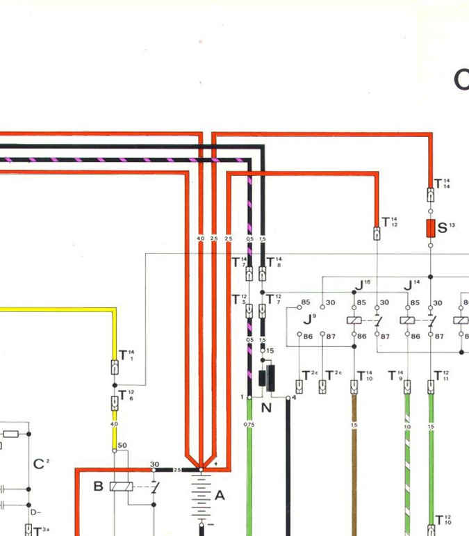 |
   |

 
|
  |
Replies
| johnorm |
Jan 22 2020, 06:33 PM
Post
#2
|
|
Newbie Group: Members Posts: 26 Joined: 28-October 18 From: Canada Member No.: 22,610 Region Association: Canada |
Guys
Thanks for the responses. Based on the information, and Tom's terrific schematic he provided, I think I will use a waterproof Fuse Block with one input and four outputs (100 AMP Max with any single fuse not to exceed 30 AMPS). The plan is:
|
|
|
|
Posts in this topic
 johnorm 914 wiring harness issue_wire size in MM Jan 20 2020, 07:56 PM
 Chi-town It's all about voltage drop. The GXL wire you... Jan 21 2020, 12:15 AM Tom Here is a small paper I put together back when I w... Jan 21 2020, 05:21 PM jcd914 Something to note about the wire sizes listed in t... Jan 21 2020, 05:48 PM
|
1 User(s) are reading this topic (1 Guests and 0 Anonymous Users)
0 Members:

|
Lo-Fi Version | Time is now: 9th June 2024 - 07:26 PM |
Invision Power Board
v9.1.4 © 2024 IPS, Inc.