|
|
|
Porsche, and the Porsche crest are registered trademarks of Dr. Ing. h.c. F. Porsche AG.
This site is not affiliated with Porsche in any way. Its only purpose is to provide an online forum for car enthusiasts. All other trademarks are property of their respective owners. |
|
|


| Charles Freeborn |
 May 22 2021, 05:02 PM May 22 2021, 05:02 PM
Post
#1
|
|
Member  Group: Members Posts: 250 Joined: 21-May 14 From: United States Member No.: 17,377 Region Association: Pacific Northwest |
My car has a downdraft fan and lowered roofline that AJRS was building in the 9o's.
When I installed a CHT I realized that it needed more airflow to the cooling fan. Methinks I'll add some scoop(s) to the equation to see if I can get the head temps down. So, location, location, location. Three images below. Where will the optimum pickup location be? I've seen a webpage done by a professor who used his AX 914 as a model and did some computer and water tank tests, but I can't read the squiggly lines well enough to tell where the best place to locate scoop(s) is. What I've come up with so far: Store bought scoops - of the kind one sees on hoods. Kinda cute, fiberglasss, would punch 4" holes through the sail panels, move other stuff out of the way and plumb to a plenum that seals to the top of the fan housing. 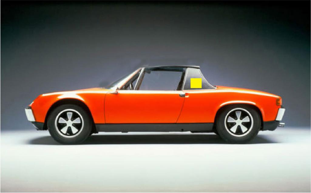 Build a lexan scoop / plenum (clear so I can see through it with rearview) and catch the airflow at the trailing edge of the roof. Opening would be roughly 2.5" x 12" to match fan opening (11" round fan) 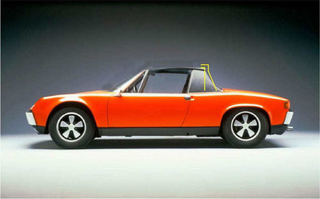 Build a lexan scoop / plenum that catches air at the leading edge of the roof, would probably run through the interior of the car and out through the rear window opening. This seems the most obtrusive to the driver ergonomics, distraction, etc. 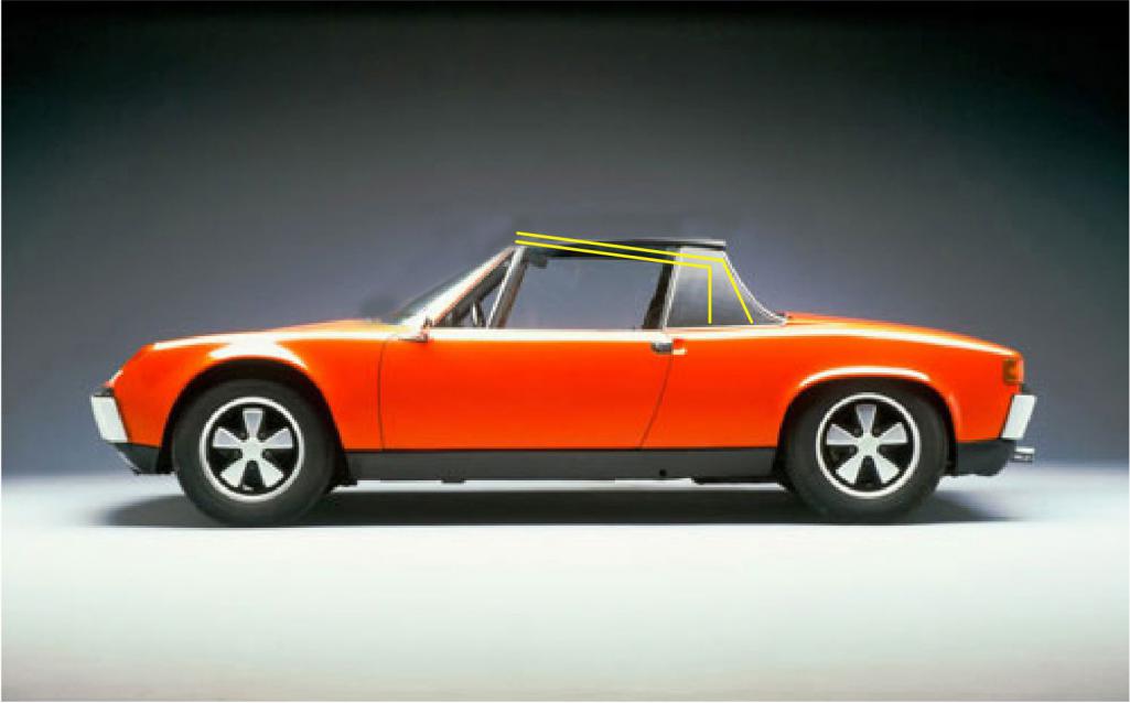 I suppose one more option would be to do a sort of hybrid of the two roof top collectors and have it punch down through the roof just in front of the rear hoop. I've seen one (also an AJRS car) done that way. It too had the raked windshield and lowered roofline as mine does. What say ye? where is the optimal pressure on a 914? BTW, I've worked with plenty of Lexan, have all the tools, so fab isn't an issue. Thanks. |
   |

 
|
  |
Replies
| Jake Raby |
May 23 2021, 03:44 PM
Post
#2
|
|
Engine Surgeon Group: Members Posts: 9,394 Joined: 31-August 03 From: Lost Member No.: 1,095 Region Association: South East States |
Remember what I told you about upper cylinder pressure over on my Type 4 FB group? Yeah, you need it.
This post has been edited by Jake Raby: May 23 2021, 03:44 PM |
|
|
|
| Charles Freeborn |
May 23 2021, 05:09 PM
Post
#3
|
|
Member Group: Members Posts: 250 Joined: 21-May 14 From: United States Member No.: 17,377 Region Association: Pacific Northwest |
QUOTE(Jake Raby @ May 23 2021, 02:44 PM)  Remember what I told you about upper cylinder pressure over on my Type 4 FB group? Yeah, you need it. Yeah, not helping. This discussion is about intake design and placement. |
|
|
|
| Jake Raby |
May 23 2021, 05:46 PM
Post
#4
|
|
Engine Surgeon Group: Members Posts: 9,394 Joined: 31-August 03 From: Lost Member No.: 1,095 Region Association: South East States |
QUOTE(Charles Freeborn @ May 23 2021, 03:09 PM) QUOTE(Jake Raby @ May 23 2021, 02:44 PM) Remember what I told you about upper cylinder pressure over on my Type 4 FB group? Yeah, you need it. Yeah, not helping. This discussion is about intake design and placement. Looks like your design is targeting forced air into the engine bay, which would increase those pressures that we conversed about. I'd consider the old SCCA Production class trick that we referred to as "the stove pipe". We used it in FP with a stock cooling system with great results, some of the stock fans only had 8 impeller blades left in place, forced air did the rest from the left front headlight bucket area, through the cabin, and into the firewall. We were tempted to try running no fan at all, but never did. The only time I have made the electric fan work was in AX on a Supervee, and once running M1 alcohol. |
|
|
|
Posts in this topic
 Charles Freeborn Engine air intake locations May 22 2021, 05:02 PM
 brant Ajrs built at least 6!pr more with the lexan s... May 22 2021, 05:13 PM
 Charles Freeborn
Ajrs built at least 6!pr more with the lexan ... May 22 2021, 06:27 PM URY914 You can see the scope here.
May 22 2021, 07:07 PM stownsen914 The farther forward on the car you put a scoop, th... May 23 2021, 08:04 AM Charles Freeborn Many thanks all. The #13 pics are heartbreaking. H... May 23 2021, 10:05 AM SirAndy I'd consider the old SCCA Production class tri... May 23 2021, 10:20 PM Charles Freeborn
[quote name='Charles Freeborn' post='2917993' dat... May 24 2021, 09:46 AM GregAmy That was a common mod for Prod 914s when they were... May 24 2021, 06:36 AM Jake Raby
That was a common mod for Prod 914s when they wer... May 24 2021, 09:38 AM ChrisFoley Something like this is extremely effective and, if... May 24 2021, 11:18 AM Charles Freeborn [quote name='ChrisFoley' date='May 24 ... May 24 2021, 12:55 PM ChrisFoley
PS, Chris, I desperately want one of your cable ... May 24 2021, 04:00 PM Charles Freeborn
PS, Chris, I desperately want one of your cable... May 24 2021, 05:35 PM URY914 You gotta get it up in the clean air. :D
May 24 2021, 06:05 PM stownsen914 One thing to consider as you design your intake / ... May 24 2021, 07:34 PM 914 Ranch My interest in this intake is cold Air. It's p... May 24 2021, 11:05 PM 914 Ranch Excuse me, the scoop.
May 24 2021, 11:20 PM 914 Ranch A pair of them.
May 24 2021, 11:23 PM Krieger What about not having a rear window, or large hole... May 25 2021, 10:56 PM
Charles Freeborn
Ajrs built at least 6!pr more with the lexan ... May 22 2021, 06:27 PM URY914 You can see the scope here.
May 22 2021, 07:07 PM stownsen914 The farther forward on the car you put a scoop, th... May 23 2021, 08:04 AM Charles Freeborn Many thanks all. The #13 pics are heartbreaking. H... May 23 2021, 10:05 AM SirAndy I'd consider the old SCCA Production class tri... May 23 2021, 10:20 PM Charles Freeborn
[quote name='Charles Freeborn' post='2917993' dat... May 24 2021, 09:46 AM GregAmy That was a common mod for Prod 914s when they were... May 24 2021, 06:36 AM Jake Raby
That was a common mod for Prod 914s when they wer... May 24 2021, 09:38 AM ChrisFoley Something like this is extremely effective and, if... May 24 2021, 11:18 AM Charles Freeborn [quote name='ChrisFoley' date='May 24 ... May 24 2021, 12:55 PM ChrisFoley
PS, Chris, I desperately want one of your cable ... May 24 2021, 04:00 PM Charles Freeborn
PS, Chris, I desperately want one of your cable... May 24 2021, 05:35 PM URY914 You gotta get it up in the clean air. :D
May 24 2021, 06:05 PM stownsen914 One thing to consider as you design your intake / ... May 24 2021, 07:34 PM 914 Ranch My interest in this intake is cold Air. It's p... May 24 2021, 11:05 PM 914 Ranch Excuse me, the scoop.
May 24 2021, 11:20 PM 914 Ranch A pair of them.
May 24 2021, 11:23 PM Krieger What about not having a rear window, or large hole... May 25 2021, 10:56 PM |
1 User(s) are reading this topic (1 Guests and 0 Anonymous Users)
0 Members:

|
Lo-Fi Version | Time is now: 12th June 2024 - 10:29 PM |
Invision Power Board
v9.1.4 © 2024 IPS, Inc.