|
|
|
Porsche, and the Porsche crest are registered trademarks of Dr. Ing. h.c. F. Porsche AG.
This site is not affiliated with Porsche in any way. Its only purpose is to provide an online forum for car enthusiasts. All other trademarks are property of their respective owners. |
|
|


| Robroe |
 Jul 23 2024, 06:04 PM Jul 23 2024, 06:04 PM
Post
#1
|
|
Member  Group: Members Posts: 77 Joined: 10-August 21 From: Wenatchee, WA Member No.: 25,793 Region Association: Pacific Northwest |
Moved from topic of first start of 10 year old build to tear down, inspect and reassemble. The 10 year old build is from a 73 1.7 to a 2270. Stroked to 78 mm and 96 mm cylinder diameter. Heads are Ham/RAT with 36 mm exhaust and 44 mm intake. Both are nicely ported.
Have torn it down to the case and checking crank end play before I split the case and pull the cam and crank. So far, everything is new and looks in good order. I'm concerned about oil passages being blocked with old assembly lube so a complete tear down and reassemble is happening. Discovered stacked cylinder spacers (4) totaling .150". So looking to replace those with single spacers. So far I can only find .160" spacers from type 4 store and may just use them as impact on compression appears minimal. Was shocked to discover crank end play is .450"! Sure glad I didn't try to start this thing. Will check again in the morning to make sure I'm checking it correctly, but I'm doing the same thing on the videos such as Ian Carrs YouTube engine builds so pretty sure I'm checking it correctly. Now to figure out what to do about that huge end play. Any thoughts about what to watch out for? |
   |

 
|
  |
Replies
| technicalninja |
Jul 27 2024, 07:32 PM
Post
#2
|
|
Advanced Member Group: Members Posts: 2,531 Joined: 31-January 23 From: Granbury Texas Member No.: 27,135 Region Association: Southwest Region |
That pic is from the Jake's crankcase video.
914werke was pointing out that there are two holes in the oil tower (my name for that part of the casting, might be mis-named, I'm weird!). We all have questions as to what it does and why two holes are needed. The most obvious reason is for crankcase ventilation. Jake can be secretive and didn't mention them. A vent already exists in this area, and it seems redundant to many of us to add more. Crankcase ventilation is CRITICAL for multiple reasons but one of them is oil leaks. If a crankcase is completely sealed it will quickly gain internal pressure from blow by gasses (all engines have some) and heat. One path for this excessive pressure is through any seals/gaskets on the engine. They blow outward... Modern engines are scavenged by the PCV system, and the "normal" method is to create a metered flow into the intake manifold. The engine SUCKS itself! (IMG:style_emoticons/default/happy11.gif) Dry sump engines have enough suction from the scavenge section of the pump that they can pull a vacuum to the point of gasket and seal failure as well. In this scenario the seals/gaskets fail inward. Hence my comment of vacuum release valves in a previous post. So, the answer to your question is Yes, this has bearing on seal/gasket life, but it is not DIRECTLY for RMS improvements alone. We would all like to see how Jake has those holes plumbed. What are they hooked up too? The really important question is why did he do it this way? He always has reasons and the level of experience he has makes him "Top Dog" to many of us. Knowing the WHY allows us to apply similar techniques to other builds. Might not be German at all. Most of us (the gear heads) are as interested in the "Journey" as the end result because we know this is NOT the only "Journey" we will travel... I'm no longer planning on taking a T4 journey. I've gone modern. Even still it's interesting enough for me to take the time to post in this thread. Now, if I had your engine, I would change my plans... You got SO LUCKY! It could be better, it could be an entire RAT, but what you have there already is what I consider the bottom of the APEX engine scale regarding T4s... Almost everyone could make 150 hp with that. Someone really good might clear 175. That LGX I mentioned makes 335 stock with a restrictive exhaust, intake, and a tune more interested in emissions over power... Now, the LGX means the ENTIRE car requires mods, almost nothing stock is applicable. It is a HUGE undertaking, a journey fit for a Ninja. (IMG:style_emoticons/default/ninja.gif) Your kitten could fit right into a stock car... |
|
|
|
| Robroe |
Jul 28 2024, 03:59 PM
Post
#3
|
|
Member Group: Members Posts: 77 Joined: 10-August 21 From: Wenatchee, WA Member No.: 25,793 Region Association: Pacific Northwest |
Picture of the grooves to drain pooled oil behind rear main seal into crankcase faster. Just used a .10" thick flat file on its edge. Then added a little channel at the bottom of the groove using a triangle file. Now off to machine shop for cleaning block halves and cylinders in cleaning tank.
 |
|
|
|
| Robroe |
Jul 28 2024, 04:13 PM
Post
#4
|
|
Member Group: Members Posts: 77 Joined: 10-August 21 From: Wenatchee, WA Member No.: 25,793 Region Association: Pacific Northwest |
Crankshaft end play dilema. When assembled, the crank end play was .045" not .004". Did a mock up of crank in bottom half of case with bearings to see if I could learn anything. The most repeatable end play measurement was .058". I understand this is just a mock up rough measurement, but so far off that I'm concerned about it. The end play shims I have are .0013, .0015 and .0015. Of course these won't fill the .045" gap when assembled.
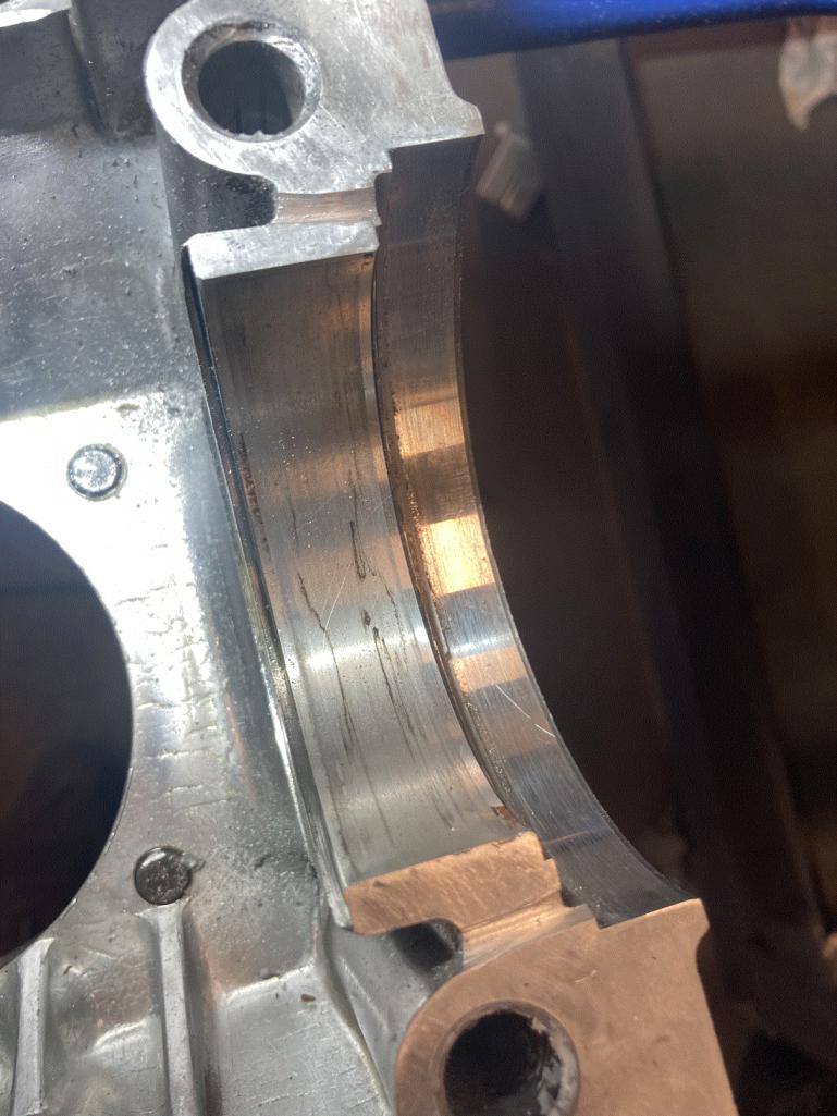
Here's my question. Since the shims rest against the outside of the rear main bearing (thrust bearing), could the rear main thrust bearing lip be too narrow? Here are picts of the mock up and bearing. If so, how would one order the proper thrust bearing lip size? 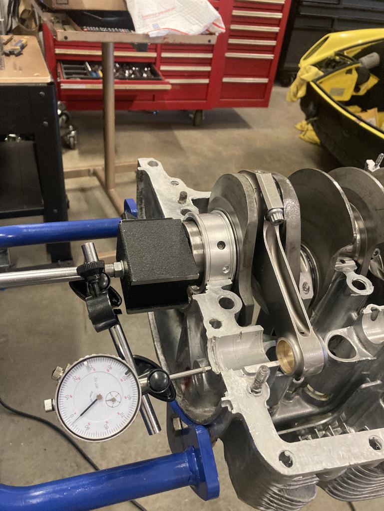 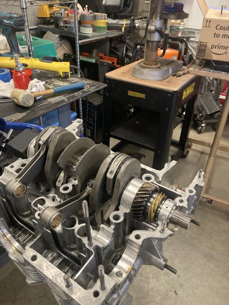 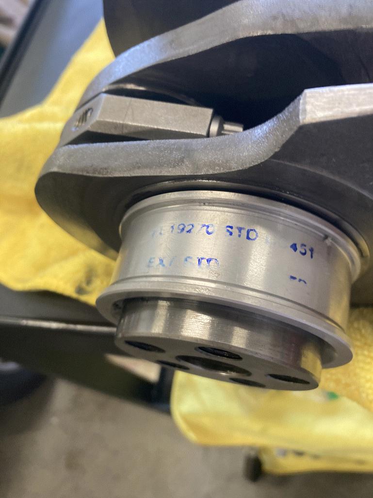 |
|
|
|
Posts in this topic
Robroe Tear Down and Reassemble Unstarted 1.7 built to 2270 Jul 23 2024, 06:04 PM wndsrfr Primary main bearing missing the thrust faces? Nea... Jul 23 2024, 06:49 PM
 Superhawk996
Primary main bearing missing the thrust faces? Ne... Jul 23 2024, 07:34 PM Robroe
Primary main bearing missing the thrust faces? N... Jul 23 2024, 08:22 PM Superhawk996 Eh . . . Sort of but not really.
Bottom line - r... Jul 23 2024, 10:33 PM Superhawk996 Have you gone through the Tom Wilson book? I know... Jul 23 2024, 10:38 PM Robroe
Have you gone through the Tom Wilson book? I kno... Jul 24 2024, 11:17 PM Superhawk996
Crank End play is .045 - .052.
Just a point o... Jul 25 2024, 07:32 AM Superhawk996 Do not force it with a case splitter. Really shou... Jul 25 2024, 05:57 AM Superhawk996 .045” of crank end play sounds like there are no... Jul 25 2024, 06:18 AM technicalninja Not having those three back there ABSOLUTELY BLOWS... Jul 25 2024, 06:38 AM Superhawk996 Proper nomenclature is 2.3L
A stock 2.0L is 1971... Jul 25 2024, 07:04 AM 73-914
Proper nomenclature is 2.3L
A stock 2.0L is 197... Jul 25 2024, 07:15 AM technicalninja I would NOT worry about determining shim selection... Jul 25 2024, 07:12 AM Superhawk996
. . .
If he gives bad advice, I WILL eviscerate ... Jul 25 2024, 07:35 AM Robroe
. . .
If he gives bad advice, I WILL eviscerate... Jul 25 2024, 12:48 PM Robroe
[quote name='Superhawk996' post='3158333' date='J... Jul 25 2024, 12:54 PM technicalninja
Proper nomenclature is 2.3L
A stock 2.0L is 197... Jul 25 2024, 07:16 AM Superhawk996 You didn’t show photo of the oil pump pick up tu... Jul 25 2024, 01:10 PM technicalninja Here's a thought I just had...
What if the cr... Jul 25 2024, 05:08 PM Robroe
Here's a thought I just had...
What if the c... Jul 26 2024, 10:50 AM Robroe Case pictures.
Jul 26 2024, 10:54 AM Robroe Crank and Cam Pictures
Jul 26 2024, 10:58 AM Robroe Rods Bearings Lifters pictures
Does this case app... Jul 26 2024, 11:04 AM Robroe Plan to send case to a machine shop today for hot ... Jul 26 2024, 11:09 AM technicalninja Oops!
Sorry for the insult!
If you could ... Jul 26 2024, 10:57 AM Superhawk996 :trophy:
Well the good news is that the internals... Jul 26 2024, 11:06 AM Superhawk996 From pictures I’m don’t think I see the Raby R... Jul 26 2024, 11:13 AM Robroe
From pictures I’m don’t think I see the Raby ... Jul 26 2024, 06:57 PM Superhawk996 Personally, I’d check at least one rod for clear... Jul 26 2024, 11:20 AM technicalninja I'd rattle all of the rods back and forth.
Ge... Jul 26 2024, 11:38 AM rhodyguy With the internal oil baffles, a newer 2.0 case? W... Jul 26 2024, 02:15 PM technicalninja His case has the thicker case registers.
That par... Jul 26 2024, 02:44 PM 914sgofast2 In looking at the cam, I noticed that there are no... Jul 26 2024, 02:53 PM Superhawk996
In looking at the cam, I noticed that there are n... Jul 26 2024, 03:30 PM Superhawk996 Previous post does being up valid topic though. W... Jul 26 2024, 03:59 PM Jack Standz You asked about case clearancing. Generally, 78mm... Jul 26 2024, 06:03 PM technicalninja
Previous post does being up valid topic though. ... Jul 26 2024, 06:26 PM technicalninja 7 minute mark in the above video I linked show it.... Jul 26 2024, 07:47 PM Superhawk996 He discusses it further at 11:55 mark Jul 26 2024, 07:54 PM Robroe
He discusses it further at 11:55 mark
Thank you... Jul 26 2024, 09:49 PM Robroe
He discusses it further at 11:55 mark
He skims o... Jul 27 2024, 12:40 AM technicalninja A few times in that vid you can see big ass holes ... Jul 26 2024, 07:59 PM Superhawk996
A few times in that vid you can see big ass holes... Jul 26 2024, 09:26 PM 914werke 7:38 you can see 2 holes on the L. side of the fil... Jul 26 2024, 09:37 PM Jack Standz
From pictures I’m don’t think I see the Raby... Jul 26 2024, 09:44 PM Jack Standz
A few times in that vid you can see big ass holes... Jul 26 2024, 09:50 PM technicalninja OK, that was weird...
Got a message that that lin... Jul 26 2024, 10:00 PM technicalninja
[quote name='Robroe' post='3158569' date='Jul 27 ... Jul 26 2024, 10:25 PM Superhawk996 It’s just another oil drain back passage at a l... Jul 27 2024, 07:39 AM technicalninja What I haven't see yet is "what does the ... Jul 27 2024, 09:41 AM Superhawk996
What I haven't see yet is "what does the... Jul 27 2024, 02:12 PM Robroe
[quote name='technicalninja' post='3158677' date=... Jul 27 2024, 03:01 PM technicalninja Yep! You're right.
I should have caught t... Jul 27 2024, 02:17 PM technicalninja Your marked lines are perfect!
I'd use a ... Jul 27 2024, 03:07 PM 914werke :idea:
Jul 27 2024, 03:17 PM Robroe
:idea:
914Werke - can a newbie ask a dumb que... Jul 27 2024, 04:30 PM Jack Standz Thanks everyone.
Don't have a mill. With t... Jul 27 2024, 03:40 PM Jack Standz
[quote name='Robroe' post='3158569' date='Jul 27... Jul 27 2024, 04:08 PM Jack Standz
It’s just another oil drain back passage at a ... Jul 27 2024, 04:26 PM technicalninja You're testing it wrong if the flywheel isn... Jul 28 2024, 05:13 PM Superhawk996 You’ve got to dig into this - agree with Ninja t... Jul 28 2024, 05:54 PM Superhawk996 Note: be careful with that woodruff key in the cr... Jul 28 2024, 06:04 PM technicalninja I think he's doing it wrong, but I do have a q... Jul 28 2024, 06:09 PM Superhawk996
Why only three shims?
"No less no more... Jul 28 2024, 06:43 PM technicalninja @Robroe
Was the flywheel bolted to the motor whe... Jul 28 2024, 06:16 PM Robroe
[b]@[url=http://www.914world.com/bbs2/index.php?s... Jul 28 2024, 08:12 PM technicalninja Most important!
The method you are using to d... Jul 28 2024, 06:30 PM Superhawk996 In defense of measuring off flywheel end. I like ... Jul 28 2024, 06:51 PM technicalninja Thinking about it he could do the exact same thing... Jul 28 2024, 06:56 PM Superhawk996 Yup always multiple ways to do it.
As long as i... Jul 28 2024, 07:04 PM technicalninja Robroe, we need pictures: do multiangle shots if p... Jul 28 2024, 07:22 PM Robroe
Robroe, we need pictures: do multiangle shots if ... Jul 31 2024, 12:57 PM technicalninja Tip for bearing indexing:
Mark ALL of the rods wi... Jul 28 2024, 08:48 PM technicalninja Have the next question regarding the CS end play i... Jul 28 2024, 09:41 PM Robroe Did another mock up today to remeasure crank end p... Jul 29 2024, 09:01 PM technicalninja Target DOWN!
Glad it's working out!
... Jul 29 2024, 09:10 PM technicalninja It looks like the clutch disc surface has seen rot... Jul 29 2024, 09:17 PM technicalninja Now for the "CHOP BUSTING BITCH!"...... Jul 29 2024, 09:42 PM Robroe [quote name='technicalninja' date='Jul... Jul 30 2024, 05:35 PM 930cabman Sounds as though you hit the jackpot with all this... Jul 30 2024, 04:49 AM technicalninja Still too early on ordering the shims IMO.
I... Jul 30 2024, 05:42 PM Front yard mechanic 79 more posts and then we can write the glossary Jul 30 2024, 06:16 PM technicalninja Need a side pic of the piston soon
Many strokers ... Jul 30 2024, 07:21 PM Robroe
Need a side pic of the piston soon
Many strokers... Jul 31 2024, 02:27 PM burton73
Need a side pic of the piston soon
Many strokers... Jul 31 2024, 03:14 PM Superhawk996 Sanity check:
Have you reviewed the Tom Wilson ... Jul 30 2024, 08:08 PM technicalninja :agree: :agree: :agree: :agree: :agree:
Read... Jul 30 2024, 08:28 PM Jack Standz
Gonna Oder gasket set and sealant kit from type ... Jul 31 2024, 07:07 AM Superhawk996 If you’re going to use that T1 pump, you need to... Jul 31 2024, 01:12 PM Robroe
If you’re going to use that T1 pump, you need t... Jul 31 2024, 02:36 PM Superhawk996
If you’re going to use that T1 pump, you need ... Jul 31 2024, 03:11 PM 930cabman
If you’re going to use that T1 pump, you need ... Jul 31 2024, 04:05 PM Jack Standz
If you’re going to use that T1 pump, you need ... Jul 31 2024, 03:35 PM Jack Standz Gene Berg oil pump with o-ring. Jul 31 2024, 04:15 PM technicalninja
[quote name='technicalninja' post='3159422' date=... Jul 31 2024, 07:21 PM Jack Standz Anyone have an idea what the hole (the one drilled... Aug 1 2024, 09:41 AM
Superhawk996
Primary main bearing missing the thrust faces? Ne... Jul 23 2024, 07:34 PM Robroe
Primary main bearing missing the thrust faces? N... Jul 23 2024, 08:22 PM Superhawk996 Eh . . . Sort of but not really.
Bottom line - r... Jul 23 2024, 10:33 PM Superhawk996 Have you gone through the Tom Wilson book? I know... Jul 23 2024, 10:38 PM Robroe
Have you gone through the Tom Wilson book? I kno... Jul 24 2024, 11:17 PM Superhawk996
Crank End play is .045 - .052.
Just a point o... Jul 25 2024, 07:32 AM Superhawk996 Do not force it with a case splitter. Really shou... Jul 25 2024, 05:57 AM Superhawk996 .045” of crank end play sounds like there are no... Jul 25 2024, 06:18 AM technicalninja Not having those three back there ABSOLUTELY BLOWS... Jul 25 2024, 06:38 AM Superhawk996 Proper nomenclature is 2.3L
A stock 2.0L is 1971... Jul 25 2024, 07:04 AM 73-914
Proper nomenclature is 2.3L
A stock 2.0L is 197... Jul 25 2024, 07:15 AM technicalninja I would NOT worry about determining shim selection... Jul 25 2024, 07:12 AM Superhawk996
. . .
If he gives bad advice, I WILL eviscerate ... Jul 25 2024, 07:35 AM Robroe
. . .
If he gives bad advice, I WILL eviscerate... Jul 25 2024, 12:48 PM Robroe
[quote name='Superhawk996' post='3158333' date='J... Jul 25 2024, 12:54 PM technicalninja
Proper nomenclature is 2.3L
A stock 2.0L is 197... Jul 25 2024, 07:16 AM Superhawk996 You didn’t show photo of the oil pump pick up tu... Jul 25 2024, 01:10 PM technicalninja Here's a thought I just had...
What if the cr... Jul 25 2024, 05:08 PM Robroe
Here's a thought I just had...
What if the c... Jul 26 2024, 10:50 AM Robroe Case pictures.
Jul 26 2024, 10:54 AM Robroe Crank and Cam Pictures
Jul 26 2024, 10:58 AM Robroe Rods Bearings Lifters pictures
Does this case app... Jul 26 2024, 11:04 AM Robroe Plan to send case to a machine shop today for hot ... Jul 26 2024, 11:09 AM technicalninja Oops!
Sorry for the insult!
If you could ... Jul 26 2024, 10:57 AM Superhawk996 :trophy:
Well the good news is that the internals... Jul 26 2024, 11:06 AM Superhawk996 From pictures I’m don’t think I see the Raby R... Jul 26 2024, 11:13 AM Robroe
From pictures I’m don’t think I see the Raby ... Jul 26 2024, 06:57 PM Superhawk996 Personally, I’d check at least one rod for clear... Jul 26 2024, 11:20 AM technicalninja I'd rattle all of the rods back and forth.
Ge... Jul 26 2024, 11:38 AM rhodyguy With the internal oil baffles, a newer 2.0 case? W... Jul 26 2024, 02:15 PM technicalninja His case has the thicker case registers.
That par... Jul 26 2024, 02:44 PM 914sgofast2 In looking at the cam, I noticed that there are no... Jul 26 2024, 02:53 PM Superhawk996
In looking at the cam, I noticed that there are n... Jul 26 2024, 03:30 PM Superhawk996 Previous post does being up valid topic though. W... Jul 26 2024, 03:59 PM Jack Standz You asked about case clearancing. Generally, 78mm... Jul 26 2024, 06:03 PM technicalninja
Previous post does being up valid topic though. ... Jul 26 2024, 06:26 PM technicalninja 7 minute mark in the above video I linked show it.... Jul 26 2024, 07:47 PM Superhawk996 He discusses it further at 11:55 mark Jul 26 2024, 07:54 PM Robroe
He discusses it further at 11:55 mark
Thank you... Jul 26 2024, 09:49 PM Robroe
He discusses it further at 11:55 mark
He skims o... Jul 27 2024, 12:40 AM technicalninja A few times in that vid you can see big ass holes ... Jul 26 2024, 07:59 PM Superhawk996
A few times in that vid you can see big ass holes... Jul 26 2024, 09:26 PM 914werke 7:38 you can see 2 holes on the L. side of the fil... Jul 26 2024, 09:37 PM Jack Standz
From pictures I’m don’t think I see the Raby... Jul 26 2024, 09:44 PM Jack Standz
A few times in that vid you can see big ass holes... Jul 26 2024, 09:50 PM technicalninja OK, that was weird...
Got a message that that lin... Jul 26 2024, 10:00 PM technicalninja
[quote name='Robroe' post='3158569' date='Jul 27 ... Jul 26 2024, 10:25 PM Superhawk996 It’s just another oil drain back passage at a l... Jul 27 2024, 07:39 AM technicalninja What I haven't see yet is "what does the ... Jul 27 2024, 09:41 AM Superhawk996
What I haven't see yet is "what does the... Jul 27 2024, 02:12 PM Robroe
[quote name='technicalninja' post='3158677' date=... Jul 27 2024, 03:01 PM technicalninja Yep! You're right.
I should have caught t... Jul 27 2024, 02:17 PM technicalninja Your marked lines are perfect!
I'd use a ... Jul 27 2024, 03:07 PM 914werke :idea:
Jul 27 2024, 03:17 PM Robroe
:idea:
914Werke - can a newbie ask a dumb que... Jul 27 2024, 04:30 PM Jack Standz Thanks everyone.
Don't have a mill. With t... Jul 27 2024, 03:40 PM Jack Standz
[quote name='Robroe' post='3158569' date='Jul 27... Jul 27 2024, 04:08 PM Jack Standz
It’s just another oil drain back passage at a ... Jul 27 2024, 04:26 PM technicalninja You're testing it wrong if the flywheel isn... Jul 28 2024, 05:13 PM Superhawk996 You’ve got to dig into this - agree with Ninja t... Jul 28 2024, 05:54 PM Superhawk996 Note: be careful with that woodruff key in the cr... Jul 28 2024, 06:04 PM technicalninja I think he's doing it wrong, but I do have a q... Jul 28 2024, 06:09 PM Superhawk996
Why only three shims?
"No less no more... Jul 28 2024, 06:43 PM technicalninja @Robroe
Was the flywheel bolted to the motor whe... Jul 28 2024, 06:16 PM Robroe
[b]@[url=http://www.914world.com/bbs2/index.php?s... Jul 28 2024, 08:12 PM technicalninja Most important!
The method you are using to d... Jul 28 2024, 06:30 PM Superhawk996 In defense of measuring off flywheel end. I like ... Jul 28 2024, 06:51 PM technicalninja Thinking about it he could do the exact same thing... Jul 28 2024, 06:56 PM Superhawk996 Yup always multiple ways to do it.
As long as i... Jul 28 2024, 07:04 PM technicalninja Robroe, we need pictures: do multiangle shots if p... Jul 28 2024, 07:22 PM Robroe
Robroe, we need pictures: do multiangle shots if ... Jul 31 2024, 12:57 PM technicalninja Tip for bearing indexing:
Mark ALL of the rods wi... Jul 28 2024, 08:48 PM technicalninja Have the next question regarding the CS end play i... Jul 28 2024, 09:41 PM Robroe Did another mock up today to remeasure crank end p... Jul 29 2024, 09:01 PM technicalninja Target DOWN!
Glad it's working out!
... Jul 29 2024, 09:10 PM technicalninja It looks like the clutch disc surface has seen rot... Jul 29 2024, 09:17 PM technicalninja Now for the "CHOP BUSTING BITCH!"...... Jul 29 2024, 09:42 PM Robroe [quote name='technicalninja' date='Jul... Jul 30 2024, 05:35 PM 930cabman Sounds as though you hit the jackpot with all this... Jul 30 2024, 04:49 AM technicalninja Still too early on ordering the shims IMO.
I... Jul 30 2024, 05:42 PM Front yard mechanic 79 more posts and then we can write the glossary Jul 30 2024, 06:16 PM technicalninja Need a side pic of the piston soon
Many strokers ... Jul 30 2024, 07:21 PM Robroe
Need a side pic of the piston soon
Many strokers... Jul 31 2024, 02:27 PM burton73
Need a side pic of the piston soon
Many strokers... Jul 31 2024, 03:14 PM Superhawk996 Sanity check:
Have you reviewed the Tom Wilson ... Jul 30 2024, 08:08 PM technicalninja :agree: :agree: :agree: :agree: :agree:
Read... Jul 30 2024, 08:28 PM Jack Standz
Gonna Oder gasket set and sealant kit from type ... Jul 31 2024, 07:07 AM Superhawk996 If you’re going to use that T1 pump, you need to... Jul 31 2024, 01:12 PM Robroe
If you’re going to use that T1 pump, you need t... Jul 31 2024, 02:36 PM Superhawk996
If you’re going to use that T1 pump, you need ... Jul 31 2024, 03:11 PM 930cabman
If you’re going to use that T1 pump, you need ... Jul 31 2024, 04:05 PM Jack Standz
If you’re going to use that T1 pump, you need ... Jul 31 2024, 03:35 PM Jack Standz Gene Berg oil pump with o-ring. Jul 31 2024, 04:15 PM technicalninja
[quote name='technicalninja' post='3159422' date=... Jul 31 2024, 07:21 PM Jack Standz Anyone have an idea what the hole (the one drilled... Aug 1 2024, 09:41 AM |
7 User(s) are reading this topic (7 Guests and 0 Anonymous Users)
0 Members:

|
Lo-Fi Version | Time is now: 13th March 2026 - 04:55 AM |
Invision Power Board
v9.1.4 © 2026 IPS, Inc.