|
|
|
Porsche, and the Porsche crest are registered trademarks of Dr. Ing. h.c. F. Porsche AG.
This site is not affiliated with Porsche in any way. Its only purpose is to provide an online forum for car enthusiasts. All other trademarks are property of their respective owners. |
|
|


| Mr Beckstar |
 Jan 25 2025, 05:37 PM Jan 25 2025, 05:37 PM
Post
#1
|
|
Newbie  Group: Members Posts: 44 Joined: 28-April 18 From: Australia Member No.: 22,082 Region Association: Australia and New Zealand |
Hi all.
I have a 4 cylinder 2 litre and am adding a remote oil filter and oil cooler circuit via a spin on adaptor attached to the stock oil filter console mount. But I noticed the oil filter bypass valve in the stock oil filter mount (circled in photo below) and now I’m concerned that, at high rpm, I’ll be bypassing the remote cooler/filter circuit. Does anyone know the bypass valve relief pressure setting? Knowing that would at least allow me to judge whether it’s an issue. 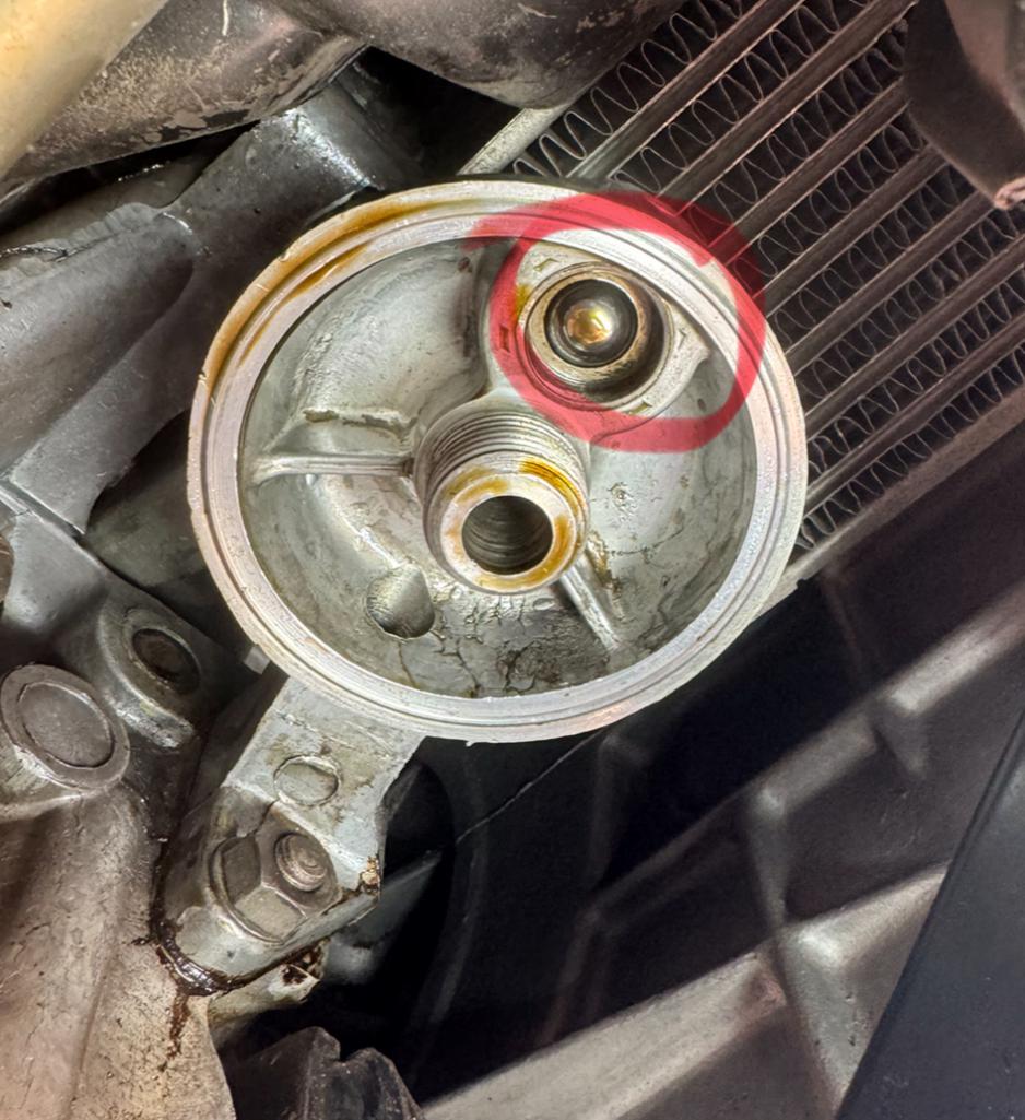 |
   |

 
|
  |
Replies
| Superhawk996 |
Jan 27 2025, 07:44 AM
Post
#2
|
|
914 Guru Group: Members Posts: 7,734 Joined: 25-August 18 From: Woods of N. Idaho Member No.: 22,428 Region Association: Galt's Gulch |
Where in the world did you come up with 3 psi?
I appreciate the idea that you’re going to try to measure the pressure drop across the filter but I’d seriously suggest you look into the accuracy of the gauges you’re using to do the measurements. If you’re using conventional dash mounted pressure gauges, the measurement will be lost in the noise and inaccuracy of the gauges. As a mechanical engineer, I will tell you that if I were trying to do what you’re proposing, it would be done on the bench and the test would be done on the filter console only without bringing an bunch of other variables into the test. If you’re that worried about bypassing the external cooler, you should be using a full flow cooler and should not be using a spin on adapter. |
|
|
|
| Mr Beckstar |
Jan 27 2025, 07:17 PM
Post
#3
|
|
Newbie Group: Members Posts: 44 Joined: 28-April 18 From: Australia Member No.: 22,082 Region Association: Australia and New Zealand |
QUOTE(Superhawk996 @ Jan 27 2025, 07:44 AM)  Where in the world did you come up with 3 psi? Montreal914 and Chris Foley said it’s “a couple of PSI” so I’ve taken 3PSI as a bypass valve setting. I can’t find any better information. QUOTE(Superhawk996 @ Jan 27 2025, 07:44 AM) I appreciate the idea that you’re going to try to measure the pressure drop across the filter but I’d seriously suggest you look into the accuracy of the gauges you’re using to do the measurements. If you’re using conventional dash mounted pressure gauges, the measurement will be lost in the noise and inaccuracy of the gauges. As a mechanical engineer, I will tell you that if I were trying to do what you’re proposing, it would be done on the bench and the test would be done on the filter console only without bringing an bunch of other variables into the test. Sorry, I mustn’t have been clear. I want to measure the extra backpressure created by the entire remote filter/cooler loop attached to the standard filter console. That includes the hose, the hose fittings, the remote filter mount, the oil cooler and the remote filter. I’m also a mechanical engineer and done a fair bit of test work/condition monitoring in my life; I’m comfortable I can get the necessary accuracy to achieve a practical result. I mean, if it turns out it’s less than 5 PSI and hard to see the drop on the instruments, then it’s probably just a case of making sure the modified stock bypass valve is set to about 10 PSI and it will be all good. And yes the accuracy of these gauges is not awesome, but I can reverse the connection points and take the average to make sure the conclusions aren’t too far skewed. QUOTE(Superhawk996 @ Jan 27 2025, 07:44 AM) If you’re that worried about bypassing the external cooler, you should be using a full flow cooler and should not be using a spin on adapter. Yes, that makes sense to me now. However, it was already installed by others. It cost me a fortune through a highly experienced VW shop that’s been trading for 50 years. I just spent a small fortune fixing all the poor workmanship, poor material selection and poor routing of all the hoses. I didn’t know about the filter bypass and nor was anything mentioned to me about the limitations of the system when I paid for the job to be done. It’s only when I worked on it myself that I noticed the filter bypass valve. I’m quite disappointed about the whole thing. Anyway, moving forward, I'm happy to spend a bit of time and effort making it work better. I don’t really want to spend another small fortune redoing the whole thing again unless I have to. |
|
|
|
| Superhawk996 |
Jan 27 2025, 08:15 PM
Post
#4
|
|
914 Guru Group: Members Posts: 7,734 Joined: 25-August 18 From: Woods of N. Idaho Member No.: 22,428 Region Association: Galt's Gulch |
QUOTE(Mr Beckstar @ Jan 27 2025, 09:17 PM) I’m also a mechanical engineer and done a fair bit of test work/condition monitoring in my life Sweet - so let’s review the check valve. It works via differential pressure that is a function of the area of the check ball exposed on the filter supply side (which is smaller) and the area of the check ball that is behind the filter (which is larger). The spring that is there is very low rate and basically exists only to keep the check ball in contact with the orifice during initial start up before oil travels through the filter media reaching the back side of the check ball. So how exactly are you going to modify the check valve to adjust the pressure at which it operates since that is a function of the exposed ball areas on each side of the orifice? Basically your options are plug it completely or design your own check valve by altering the ratio of exposed check ball areas. Food for thought. |
|
|
|
| Mr Beckstar |
Jan 28 2025, 01:31 AM
Post
#5
|
|
Newbie Group: Members Posts: 44 Joined: 28-April 18 From: Australia Member No.: 22,082 Region Association: Australia and New Zealand |
QUOTE(Superhawk996 @ Jan 27 2025, 08:15 PM) QUOTE(Mr Beckstar @ Jan 27 2025, 09:17 PM) I’m also a mechanical engineer and done a fair bit of test work/condition monitoring in my life Sweet - so let’s review the check valve. It works via differential pressure that is a function of the area of the check ball exposed on the filter supply side (which is smaller) and the area of the check ball that is behind the filter (which is larger). The spring that is there is very low rate and basically exists only to keep the check ball in contact with the orifice during initial start up before oil travels through the filter media reaching the back side of the check ball. So how exactly are you going to modify the check valve to adjust the pressure at which it operates since that is a function of the exposed ball areas on each side of the orifice? Basically your options are plug it completely or design your own check valve by altering the ratio of exposed check ball areas. Food for thought. To modify the check valve relief pressure, change the spring rate. Ie a heavier spring to increase the relief pressure. When the valve is closed, the effective area of the valve is the area of the hole on which the ball seats. The edges of the ball that are larger than the hole have the same pressure on both sides, which cancels each other out. So it’s just the hole diameter that’s used in the [pressure=force/area] formula. The spring will dictate the [force], the [area] is calculated as mentioned anbove, and that allows calculation of relief [pressure]. I know there are other factors when the valve opens eg pressure drop on opposite sides of the ball when oil flows through the valve, but I don’t think that sort of accuracy is needed here. I’m more concerned about opening pressure. |
|
|
|
Posts in this topic
 Mr Beckstar Bypass Valve on Stock Oil Filter Console Jan 25 2025, 05:37 PM
 Montreal914 Good concern and already discussed here in the pas... Jan 25 2025, 06:09 PM
 Mr Beckstar
Good concern and already discussed here in the pa... Jan 26 2025, 05:16 AM Montreal914 Looks like it is a couple of psi.
Read @[url=htt... Jan 26 2025, 09:55 AM Superhawk996 I hate chiming in on this because I don’t have a... Jan 26 2025, 12:38 PM technicalninja :agree:
I believe every single ICE engine with b... Jan 26 2025, 01:00 PM Mr Beckstar Thanks for the great responses everyone :D
If i... Jan 27 2025, 07:11 AM Superhawk996
The spring will dictate the [force], the [area] i... Jan 28 2025, 07:54 AM Mr Beckstar
The spring will dictate the [force], the [area] ... Jan 29 2025, 04:00 AM emerygt350 And why on earth would you want to send cold oil t... Jan 27 2025, 06:22 PM Mr Beckstar
And why on earth would you want to send cold oil ... Jan 27 2025, 07:22 PM technicalninja
Where in the world did you come up with 3 psi?
... Jan 27 2025, 08:19 PM Mr Beckstar
Sadly, the old saying "if you want somethin... Jan 28 2025, 01:35 AM technicalninja
I’m also a mechanical engineer and done a fai... Jan 27 2025, 08:25 PM Mr Beckstar
[quote name='Superhawk996' post='3189070' date='J... Jan 28 2025, 01:38 AM GregAmy Can I insert just a couple basic questions here?
... Jan 28 2025, 08:11 AM Mr Beckstar
Can I insert just a couple basic questions here?
... Jan 29 2025, 04:16 AM Superhawk996 I don’t want to answer for OP but my understandi... Jan 28 2025, 10:15 AM GregAmy
I don’t want to answer for OP but my understand... Jan 28 2025, 10:23 AM Superhawk996
I suggest it's a non-issue. But if you're... Jan 28 2025, 10:27 AM Mr Beckstar
I don’t want to answer for OP but my understan... Jan 29 2025, 04:26 AM Mr Beckstar
…I view this discussion as largely theoretica... Mar 11 2025, 04:17 AM Mr Beckstar I looked at those two links and they’re not rele... Jan 29 2025, 04:24 AM Mr Beckstar The oil filter bypass valve piqued my interest so ... Feb 21 2025, 03:31 AM Mr Beckstar The above pressure readings were measured using th... Feb 21 2025, 04:10 AM Superhawk996 Interesting data points.
Food for thought on the ... Feb 21 2025, 08:40 AM Mr Beckstar Okay, I just used a brand new gauge with 0-15 PSI ... Mar 11 2025, 03:13 AM Mr Beckstar Next step is to fit the two pressure tappings into... Mar 11 2025, 03:29 AM Superhawk996 You’re in uncharted territory as far as I know. ... Mar 11 2025, 07:06 AM Mr Beckstar
You’re in uncharted territory as far as I know.... Mar 12 2025, 02:29 AM Superhawk996 Food for thought
If you look at histograms of av... Mar 12 2025, 07:55 AM Mr Beckstar
Food for thought
If you look at histograms of a... Mar 13 2025, 01:49 AM Superhawk996
At 68 MPH, the engine’s doing 4,200 rpm. Bei... Mar 13 2025, 06:46 AM
Mr Beckstar
Good concern and already discussed here in the pa... Jan 26 2025, 05:16 AM Montreal914 Looks like it is a couple of psi.
Read @[url=htt... Jan 26 2025, 09:55 AM Superhawk996 I hate chiming in on this because I don’t have a... Jan 26 2025, 12:38 PM technicalninja :agree:
I believe every single ICE engine with b... Jan 26 2025, 01:00 PM Mr Beckstar Thanks for the great responses everyone :D
If i... Jan 27 2025, 07:11 AM Superhawk996
The spring will dictate the [force], the [area] i... Jan 28 2025, 07:54 AM Mr Beckstar
The spring will dictate the [force], the [area] ... Jan 29 2025, 04:00 AM emerygt350 And why on earth would you want to send cold oil t... Jan 27 2025, 06:22 PM Mr Beckstar
And why on earth would you want to send cold oil ... Jan 27 2025, 07:22 PM technicalninja
Where in the world did you come up with 3 psi?
... Jan 27 2025, 08:19 PM Mr Beckstar
Sadly, the old saying "if you want somethin... Jan 28 2025, 01:35 AM technicalninja
I’m also a mechanical engineer and done a fai... Jan 27 2025, 08:25 PM Mr Beckstar
[quote name='Superhawk996' post='3189070' date='J... Jan 28 2025, 01:38 AM GregAmy Can I insert just a couple basic questions here?
... Jan 28 2025, 08:11 AM Mr Beckstar
Can I insert just a couple basic questions here?
... Jan 29 2025, 04:16 AM Superhawk996 I don’t want to answer for OP but my understandi... Jan 28 2025, 10:15 AM GregAmy
I don’t want to answer for OP but my understand... Jan 28 2025, 10:23 AM Superhawk996
I suggest it's a non-issue. But if you're... Jan 28 2025, 10:27 AM Mr Beckstar
I don’t want to answer for OP but my understan... Jan 29 2025, 04:26 AM Mr Beckstar
…I view this discussion as largely theoretica... Mar 11 2025, 04:17 AM Mr Beckstar I looked at those two links and they’re not rele... Jan 29 2025, 04:24 AM Mr Beckstar The oil filter bypass valve piqued my interest so ... Feb 21 2025, 03:31 AM Mr Beckstar The above pressure readings were measured using th... Feb 21 2025, 04:10 AM Superhawk996 Interesting data points.
Food for thought on the ... Feb 21 2025, 08:40 AM Mr Beckstar Okay, I just used a brand new gauge with 0-15 PSI ... Mar 11 2025, 03:13 AM Mr Beckstar Next step is to fit the two pressure tappings into... Mar 11 2025, 03:29 AM Superhawk996 You’re in uncharted territory as far as I know. ... Mar 11 2025, 07:06 AM Mr Beckstar
You’re in uncharted territory as far as I know.... Mar 12 2025, 02:29 AM Superhawk996 Food for thought
If you look at histograms of av... Mar 12 2025, 07:55 AM Mr Beckstar
Food for thought
If you look at histograms of a... Mar 13 2025, 01:49 AM Superhawk996
At 68 MPH, the engine’s doing 4,200 rpm. Bei... Mar 13 2025, 06:46 AM |
1 User(s) are reading this topic (1 Guests and 0 Anonymous Users)
0 Members:

|
Lo-Fi Version | Time is now: 13th March 2026 - 01:13 AM |
Invision Power Board
v9.1.4 © 2026 IPS, Inc.