|
|
|
Porsche, and the Porsche crest are registered trademarks of Dr. Ing. h.c. F. Porsche AG.
This site is not affiliated with Porsche in any way. Its only purpose is to provide an online forum for car enthusiasts. All other trademarks are property of their respective owners. |
|
|


| L-Jet914 |
 Feb 25 2025, 11:35 PM Feb 25 2025, 11:35 PM
Post
#1
|
|
Member  Group: Members Posts: 405 Joined: 24-October 12 From: Davis, CA Member No.: 15,080 Region Association: Northern California |
I was installing my new ignition and FI harnesses today and I decided to look back at the vacuum hose routing diagram on Jeff Bowlsby's website. I knew my vacuum hose routing had been modified by whatever technician worked on my father's 74 914 1.8 years ago. I noticed that they teed the vacuum retard side of the vacuum advance into ported vacuum off of the intake plenum. According to the vacuum routing hose diagram, it's supposed to be connected to the rear port of the throttle body (which only gets vacuum after the throttle plate moves off idle). Would there be any reason the technician did this? I will end up rerouting the vacuum hose to the proper location. I'm just curious as to why it was modified for whatever reason. So would my 74 1.8 be considered a early or late 1.8? According to the late diagram and the throttle body that is in the car, the hose should route to the front port instead of the rear port.
The part number on the throttle body in the car 022133067C which fits either a Super Beetle 75-79, 76-83 Bus, or 83-84 Vanagon (two port t-body). According to the PET on AA's website shows two different throttle bodies 022133062L or 022133062S for California spec 1.8L 914s. The Porsche PET does not list a throttle body part number for the 1.8, only the 1.7 and 2.0s. Curious as to why someone would put the wrong part number throttle body on my 914, though it does have the 3 pin throttle position sensor. Port setup would be indicative of late 74 because the required port (front of throttle body pointing toward front of vehicle) is behind the throttle plate. Attached thumbnail(s) 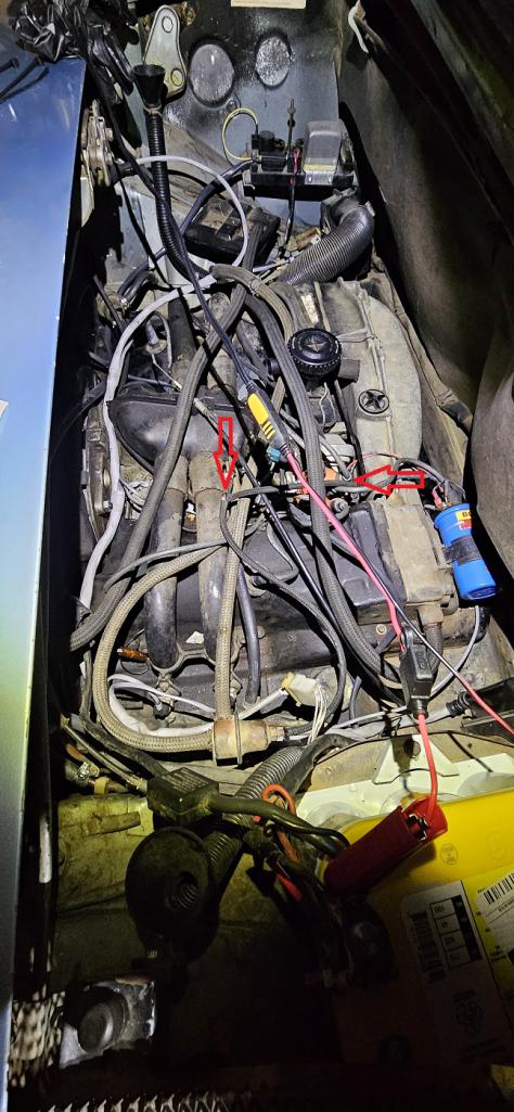 Attached image(s) 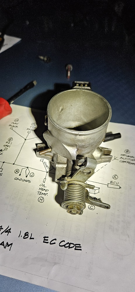  
|
   |

 
|
  |
Replies
| L-Jet914 |
Mar 4 2025, 12:35 AM
Post
#2
|
|
Member Group: Members Posts: 405 Joined: 24-October 12 From: Davis, CA Member No.: 15,080 Region Association: Northern California |
Sorry for opening up a can of worms haha. When I ran the part number on the throttle body that is in the car, it fit the vehicles listed earlier. The retard side of the vac can is connected to a second vacuum T fitted in between the line that is meant for the FPR and decel valve. The retard side of the t-body was capped off lord known when. Vac advance was already connected to the port facing the rear of the vehicle when I initially started replacing vacuum lines years ago to fix vacuum leaks in the system. According to your vacuum hose routing diagrams Michael, there should be only 1 T-fitting off of the intake plenum which connects the FPR and decel valve which I will be restoring to factory configuration. I will be reconnecting the retard side of the can to the port facing the front of the vehicle once I receive my new vacuum hose that I have ordered. Once all that is done, the vacuum hoses will be routed correctly to EC-B configuration with no additions.
|
|
|
|
| emerygt350 |
Mar 4 2025, 08:39 AM
Post
#3
|
|
Advanced Member Group: Members Posts: 3,661 Joined: 20-July 21 From: Upstate, NY Member No.: 25,740 Region Association: North East States |
QUOTE(L-Jet914 @ Mar 4 2025, 01:35 AM)  Sorry for opening up a can of worms haha. When I ran the part number on the throttle body that is in the car, it fit the vehicles listed earlier. The retard side of the vac can is connected to a second vacuum T fitted in between the line that is meant for the FPR and decel valve. The retard side of the t-body was capped off lord known when. Vac advance was already connected to the port facing the rear of the vehicle when I initially started replacing vacuum lines years ago to fix vacuum leaks in the system. According to your vacuum hose routing diagrams Michael, there should be only 1 T-fitting off of the intake plenum which connects the FPR and decel valve which I will be restoring to factory configuration. I will be reconnecting the retard side of the can to the port facing the front of the vehicle once I receive my new vacuum hose that I have ordered. Once all that is done, the vacuum hoses will be routed correctly to EC-B configuration with no additions. Make sure you double check that port is doing what it is supposed to. Vacuum at idle and not when you rev the motor. What bothers me about the loss of advance is originally they were supposed to 'fight' each other inside the vac can, but when you remove the advance that can't happen. Obviously, the engineers didn't think that was a problem, but I still wonder about it. |
 |
|
| L-Jet914 |
Mar 9 2025, 11:16 PM
Post
#4
|
|
Member Group: Members Posts: 405 Joined: 24-October 12 From: Davis, CA Member No.: 15,080 Region Association: Northern California |
QUOTE(emerygt350 @ Mar 4 2025, 07:39 AM) QUOTE(L-Jet914 @ Mar 4 2025, 01:35 AM) Sorry for opening up a can of worms haha. When I ran the part number on the throttle body that is in the car, it fit the vehicles listed earlier. The retard side of the vac can is connected to a second vacuum T fitted in between the line that is meant for the FPR and decel valve. The retard side of the t-body was capped off lord known when. Vac advance was already connected to the port facing the rear of the vehicle when I initially started replacing vacuum lines years ago to fix vacuum leaks in the system. According to your vacuum hose routing diagrams Michael, there should be only 1 T-fitting off of the intake plenum which connects the FPR and decel valve which I will be restoring to factory configuration. I will be reconnecting the retard side of the can to the port facing the front of the vehicle once I receive my new vacuum hose that I have ordered. Once all that is done, the vacuum hoses will be routed correctly to EC-B configuration with no additions. Make sure you double check that port is doing what it is supposed to. Vacuum at idle and not when you rev the motor. What bothers me about the loss of advance is originally they were supposed to 'fight' each other inside the vac can, but when you remove the advance that can't happen. Obviously, the engineers didn't think that was a problem, but I still wonder about it. I fired up the ol 914 last night after installing new runs of cloth braided vacuum hose per the vacuum diagrams that @wonkipop made to EC-B specifications. The front port (facing the front of the vehicle) has vacuum at idle for the retard side of the vacuum can and the rear port (facing rear of the vehicle) gets vacuum when you come off idle for the vac advance side. Thank you again everyone for your inputs. My 914 now has vacuum hoses routed exactly like @wonkipop diagrams. I removed the extra inline vacuum T that some technician added many years ago. I got the new vacuum hoses (3.5mm and 4.5mm) from Auto Atlanta as they had the cheapest/foot cost from all the other places I looked online. |
|
|
|
Posts in this topic
 L-Jet914 vacuum hose routing question Feb 25 2025, 11:35 PM
 wonkipop the authorative hose diagrams are here mate. bott... Feb 26 2025, 04:37 AM
 L-Jet914
the authorative hose diagrams are here mate. bot... Feb 27 2025, 10:21 PM JeffBowlsby Michael is the L-Jet MAN. That diagram on my site... Feb 26 2025, 09:09 AM StarBear
Michael is the L-Jet MAN. That diagram on my sit... Feb 26 2025, 02:04 PM wonkipop
Michael is the L-Jet MAN. That diagram on my si... Feb 26 2025, 02:39 PM wonkipop @L-Jet914
i looked up the PET i have on file and... Feb 26 2025, 02:12 PM wonkipop @L-Jet914
if you think i have mixed up the let... Feb 26 2025, 02:29 PM wonkipop for your interest @L-Jet914 .
here is an image ... Feb 26 2025, 03:52 PM Fazasport I have a 1976 914 2.0 with D-Jet and no modificati... Feb 27 2025, 06:17 AM wonkipop
I have a 1976 914 2.0 with D-Jet and no modificat... Feb 27 2025, 06:21 PM wonkipop @L-Jet914
david - that throttle body looks ident... Feb 28 2025, 10:57 AM L-Jet914
[b]@[url=http://www.914world.com/bbs2/index.php?s... Feb 28 2025, 07:57 PM Rob-O Beyond all the hooking up of vacuum lines, the cha... Mar 3 2025, 07:35 AM wonkipop
Beyond all the hooking up of vacuum lines, the ch... Mar 3 2025, 05:53 PM L-Jet914
Sorry for opening up a can of worms haha. When I... Mar 4 2025, 04:39 PM wonkipop
Sorry for opening up a can of worms haha. When I... Mar 5 2025, 04:34 AM emerygt350 Maybe my next CAD project. Mar 4 2025, 05:47 PM L-Jet914
Maybe my next CAD project.
Oooo. That would be a... Mar 4 2025, 05:54 PM emerygt350 I think I might have to try this project. Mar 4 2025, 07:25 PM emerygt350 Yes, there is definitely that "driving a lazy... Mar 5 2025, 05:25 AM
L-Jet914
the authorative hose diagrams are here mate. bot... Feb 27 2025, 10:21 PM JeffBowlsby Michael is the L-Jet MAN. That diagram on my site... Feb 26 2025, 09:09 AM StarBear
Michael is the L-Jet MAN. That diagram on my sit... Feb 26 2025, 02:04 PM wonkipop
Michael is the L-Jet MAN. That diagram on my si... Feb 26 2025, 02:39 PM wonkipop @L-Jet914
i looked up the PET i have on file and... Feb 26 2025, 02:12 PM wonkipop @L-Jet914
if you think i have mixed up the let... Feb 26 2025, 02:29 PM wonkipop for your interest @L-Jet914 .
here is an image ... Feb 26 2025, 03:52 PM Fazasport I have a 1976 914 2.0 with D-Jet and no modificati... Feb 27 2025, 06:17 AM wonkipop
I have a 1976 914 2.0 with D-Jet and no modificat... Feb 27 2025, 06:21 PM wonkipop @L-Jet914
david - that throttle body looks ident... Feb 28 2025, 10:57 AM L-Jet914
[b]@[url=http://www.914world.com/bbs2/index.php?s... Feb 28 2025, 07:57 PM Rob-O Beyond all the hooking up of vacuum lines, the cha... Mar 3 2025, 07:35 AM wonkipop
Beyond all the hooking up of vacuum lines, the ch... Mar 3 2025, 05:53 PM L-Jet914
Sorry for opening up a can of worms haha. When I... Mar 4 2025, 04:39 PM wonkipop
Sorry for opening up a can of worms haha. When I... Mar 5 2025, 04:34 AM emerygt350 Maybe my next CAD project. Mar 4 2025, 05:47 PM L-Jet914
Maybe my next CAD project.
Oooo. That would be a... Mar 4 2025, 05:54 PM emerygt350 I think I might have to try this project. Mar 4 2025, 07:25 PM emerygt350 Yes, there is definitely that "driving a lazy... Mar 5 2025, 05:25 AM |
3 User(s) are reading this topic (3 Guests and 0 Anonymous Users)
0 Members:

|
Lo-Fi Version | Time is now: 30th June 2026 - 05:06 PM |
Invision Power Board
v9.1.4 © 2026 IPS, Inc.