|
|
|
Porsche, and the Porsche crest are registered trademarks of Dr. Ing. h.c. F. Porsche AG.
This site is not affiliated with Porsche in any way. Its only purpose is to provide an online forum for car enthusiasts. All other trademarks are property of their respective owners. |
|
|


| GeorgeKopf |
 May 26 2025, 04:25 PM May 26 2025, 04:25 PM
Post
#1
|
|
Member  Group: Members Posts: 263 Joined: 9-February 21 From: Princeton, NJ Member No.: 25,186 Region Association: MidAtlantic Region |
I'm wring my 1973 wiring harness and have a bunch of things installed which seem to be working correctly (i.e. headlights (high & low beam), headlight motors, turn signals, running lights, tail lights)
But (IMG:style_emoticons/default/bootyshake.gif) the turn signal indicators are always on! I've traced the flow of current from the fuse panel (red with white stripe) to the hazard switch, from there (red) to the relay and from there to the turn signal indicators (blue with white stripe). 47 is the relay 31 is the hazard switch 22 is the turn signal lights 26 is the steering column switch 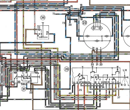 I have two relays and both seem to work fine. When I pull out the hazard switch the indicators and lights all blink. When I set the turn signal that side blinks. I have two hazard switches and both behave the same way. As soon as I connect the red and red/white wires the turn signal indicators come on. With the knob pushed in, I have continuity between the red/white (power in) and the red (power out to the relay). With the knob pulled out, I have continuity between the black/red (power in) and the red (power out to the relay). (IMG:style_emoticons/default/confused24.gif) More information: I have cleaned all grounding studs. I disassembled one of the relays and cleaned it. If I disconnect all of the wires from the hazard switch except for the red/white and the red, the signal indicators come on and stay on. Doesn't this mean that my relay is bad? It should be getting power so that it can feed the turn signal indicators when the turn signals are set. It seems that the relay is allowing the input power to the blue/white wires when it shouldn't. If so, is there a good way to test or repair them? Thanks in advance for any advice. George |
   |

 
|
  |
Replies
| GeorgeKopf |
May 28 2025, 09:40 AM
Post
#2
|
|
Member Group: Members Posts: 263 Joined: 9-February 21 From: Princeton, NJ Member No.: 25,186 Region Association: MidAtlantic Region |
@Spoke
If I remove the flasher relay, the indicators do not come on with the key. With the flasher relay installed, I get power on the blue/white wire to both indicators. Also, disconnecting the turn signal switch didn't make any difference. Thanks. George |
|
|
|
| Spoke |
May 28 2025, 02:43 PM
Post
#3
|
|
Jerry Group: Members Posts: 7,413 Joined: 29-October 04 From: Allentown, PA Member No.: 3,031 Region Association: None |
QUOTE(GeorgeKopf @ May 28 2025, 11:40 AM)  @Spoke If I remove the flasher relay, the indicators do not come on with the key. With the flasher relay installed, I get power on the blue/white wire to both indicators. Also, disconnecting the turn signal switch didn't make any difference. Thanks. George I would expect the indicators to be off with the relay removed. Quite honestly, I'd bypass the K/C/C2 pin on the relay and just ground the common connection of the indicators to the tach ground. I did this on my '71. I'm still using the OEM flasher with all LEDs with no issues. If you do change to external LEDs the function of K/C/C2 is lost. K/C/C2 is active in the relays as a safety feature to alert the driver of a burned exterior turnsignal bulb. If a bulb is burned out, the relay will not power K/C/C2 during flashing and both indicators will flash together indicating a burned bulb. An easy workaround which I did on my 914 is to remove the common wire at the indicators and tape them off. Then make a pigtail like shown below. The piggyback connector goes under the tach ground (brown wire) and the 2 female spades go to each indicator. The indicators will flash opposite (L on for right turnsignal; R on for lefts). This is easily fixed by pulling the entire light assembly out and put it in the opposite hole. Here's spades for the mod. This is the ground piggyback connector. You need 1 of these. Piggyback Spade This is for the bulb spades. You'll need 2. Female Spade Attached thumbnail(s) 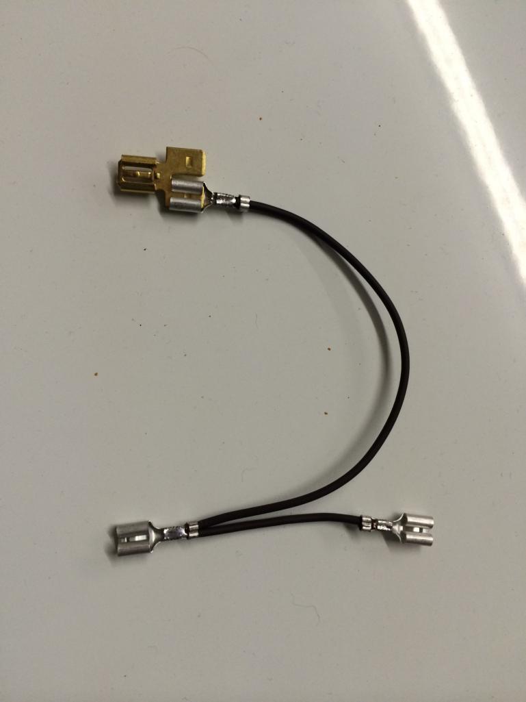 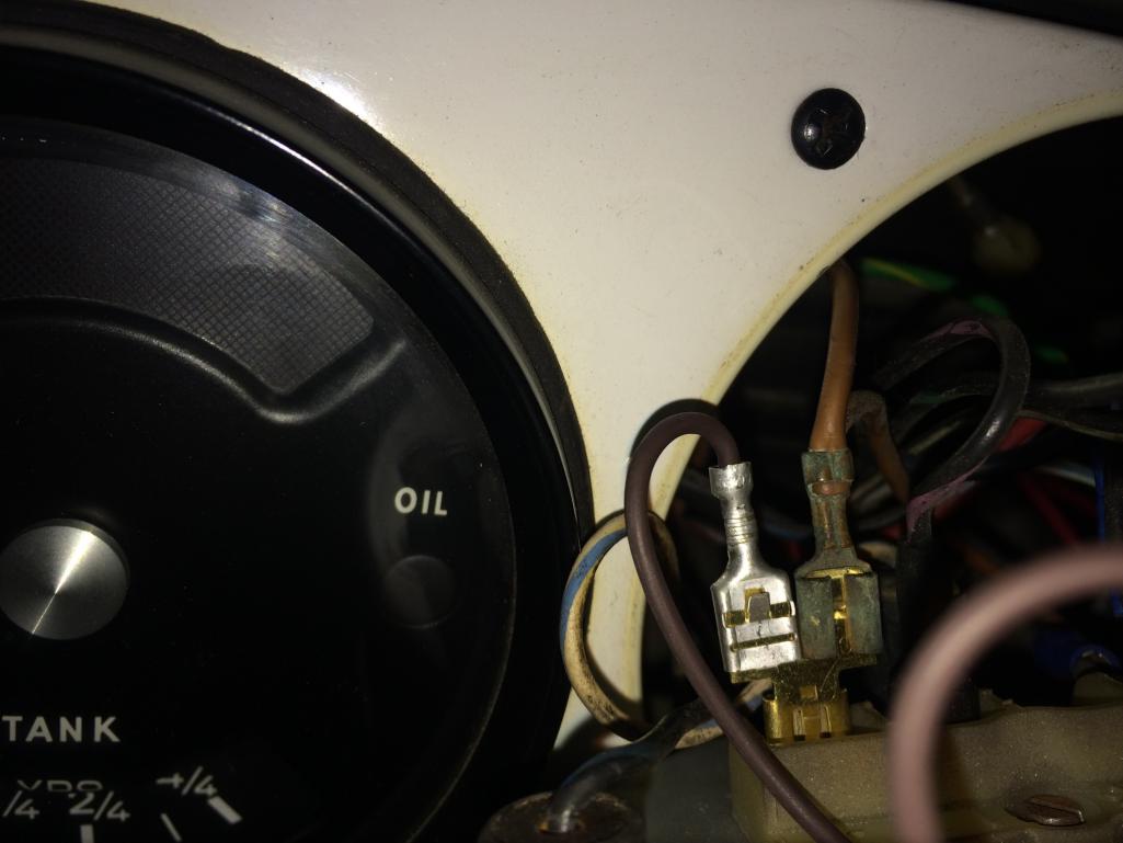
|
|
|
|
Posts in this topic
 GeorgeKopf Turn signal indicator lights come on with key May 26 2025, 04:25 PM
 904svo jUST A wag check that the brown wire is connect to... May 26 2025, 05:21 PM Superhawk996 Simplified wiring diagram from Spoke
Take note... May 27 2025, 05:26 AM Superhawk996
If I disconnect all of the wires from the hazard... May 27 2025, 05:29 AM rfinegan ON or blinking?
My problems have allows been a bad... May 27 2025, 05:51 AM
904svo jUST A wag check that the brown wire is connect to... May 26 2025, 05:21 PM Superhawk996 Simplified wiring diagram from Spoke
Take note... May 27 2025, 05:26 AM Superhawk996
If I disconnect all of the wires from the hazard... May 27 2025, 05:29 AM rfinegan ON or blinking?
My problems have allows been a bad... May 27 2025, 05:51 AM
 Superhawk996
See diode in the flasher circuit.
??
There is... May 27 2025, 06:00 AM rfinegan My bad, not a diode but replacement did fix my lig... May 27 2025, 08:55 AM GeorgeKopf @Superhawk996
Thanks for the simplified diagram. ... May 27 2025, 07:11 PM Superhawk996 If you’ve already tried 2 flasher relays, and it... May 27 2025, 10:33 PM GeorgeKopf @Superhawk996
I was thinking how I might bench t... May 28 2025, 08:46 AM Superhawk996
Do you know which connector on the unit represen... May 28 2025, 09:34 AM Spoke
But :bootyshake: the turn signal indicators are a... May 28 2025, 09:17 AM rfinegan I did use a LED ready hazard flasher, so when I up... May 28 2025, 11:32 AM GeorgeKopf @rfinegan
This is very good information. I... May 28 2025, 11:51 AM GeorgeKopf @Spoke You said:
"An easy workaround which... May 28 2025, 07:15 PM Superhawk996
Between 49 and C:......resistance is 850 ohms...... May 29 2025, 02:42 AM Spoke
My flasher relay is only labeled:
....49
49a....... May 29 2025, 07:30 AM GeorgeKopf @Spoke
Do you open up a stock EP26 and modify it... May 29 2025, 07:47 AM Spoke
[b]@[url=http://www.914world.com/bbs2/index.php?s... May 29 2025, 08:24 AM GeorgeKopf
Yes. I show how to make the mod on my website if ... May 29 2025, 09:52 AM Spoke
Yes. I show how to make the mod on my website if... May 29 2025, 08:00 PM GeorgeKopf
I'll buy one of your LED relays.
I installe... Jun 8 2025, 07:37 PM GeorgeKopf Before I start a new thread .....
<edit> I... May 31 2025, 04:34 PM GeorgeKopf @Spokes
<edit> I just found the answer on... May 31 2025, 07:09 PM Spoke
@Spokes
<edit> I just found the answer o... May 31 2025, 09:05 PM BillC
[quote name='GeorgeKopf' post='3208274' date='May... Jun 2 2025, 07:09 PM Superhawk996 :trophy:
Good job doing the basic troubleshootin... Jun 9 2025, 07:52 PM
Superhawk996
See diode in the flasher circuit.
??
There is... May 27 2025, 06:00 AM rfinegan My bad, not a diode but replacement did fix my lig... May 27 2025, 08:55 AM GeorgeKopf @Superhawk996
Thanks for the simplified diagram. ... May 27 2025, 07:11 PM Superhawk996 If you’ve already tried 2 flasher relays, and it... May 27 2025, 10:33 PM GeorgeKopf @Superhawk996
I was thinking how I might bench t... May 28 2025, 08:46 AM Superhawk996
Do you know which connector on the unit represen... May 28 2025, 09:34 AM Spoke
But :bootyshake: the turn signal indicators are a... May 28 2025, 09:17 AM rfinegan I did use a LED ready hazard flasher, so when I up... May 28 2025, 11:32 AM GeorgeKopf @rfinegan
This is very good information. I... May 28 2025, 11:51 AM GeorgeKopf @Spoke You said:
"An easy workaround which... May 28 2025, 07:15 PM Superhawk996
Between 49 and C:......resistance is 850 ohms...... May 29 2025, 02:42 AM Spoke
My flasher relay is only labeled:
....49
49a....... May 29 2025, 07:30 AM GeorgeKopf @Spoke
Do you open up a stock EP26 and modify it... May 29 2025, 07:47 AM Spoke
[b]@[url=http://www.914world.com/bbs2/index.php?s... May 29 2025, 08:24 AM GeorgeKopf
Yes. I show how to make the mod on my website if ... May 29 2025, 09:52 AM Spoke
Yes. I show how to make the mod on my website if... May 29 2025, 08:00 PM GeorgeKopf
I'll buy one of your LED relays.
I installe... Jun 8 2025, 07:37 PM GeorgeKopf Before I start a new thread .....
<edit> I... May 31 2025, 04:34 PM GeorgeKopf @Spokes
<edit> I just found the answer on... May 31 2025, 07:09 PM Spoke
@Spokes
<edit> I just found the answer o... May 31 2025, 09:05 PM BillC
[quote name='GeorgeKopf' post='3208274' date='May... Jun 2 2025, 07:09 PM Superhawk996 :trophy:
Good job doing the basic troubleshootin... Jun 9 2025, 07:52 PM |
1 User(s) are reading this topic (1 Guests and 0 Anonymous Users)
0 Members:

|
Lo-Fi Version | Time is now: 28th July 2026 - 02:19 AM |
Invision Power Board
v9.1.4 © 2026 IPS, Inc.