
 AC for my Six Conversion, Improvements |
|
|

|
Porsche, and the Porsche crest are registered trademarks of Dr. Ing. h.c. F. Porsche AG.
This site is not affiliated with Porsche in any way. Its only purpose is to provide an online forum for car enthusiasts. All other trademarks are property of their respective owners. |
|
|

| Larry.Hubby |
 Nov 3 2026, 01:35 AM
Post
#1
|
|
Member who doesn't post much, but has a long time in 914s  Group: Members Posts: 192 Joined: 24-November 04 From: Palo Alto, CA Member No.: 3,172 Region Association: Northern California  |
Several years ago I posted several threads about a custom air conditioning system I built for my 1970 914 that I converted to a six with a ’78 911SC engine and transmission quite some time before. For reference, here are links to those threads:
Introduction Mounting the Compressor Locating and Mounting the Condensor Fitting the Evaporator Under the Cowl Controls Any of you that may have read those posts may recall that there were a few things that I was not satisfied with about the resulting system, and the subsequent time since then has only served to enlarge that list. When the Covid pandemic hit in early 2020 and most competitive entertainment options such as travel, performances, eating out, etc. became effectively unavailable, I found myself with no excuse to avoid trying to fix these problems along with everything else in the way of things I’d resolved to do to the car “someday”. “Someday”, it seems, had suddenly become “now”. It would be nice to be able to say that I simply wrote down a to-do list and worked on it until I got to the end, but most of you know that that is not how this sort of thing goes. Initial efforts uncover additional issues, and for quite a while the to-do list grows rather than shrinks. In my case this included discovering a broken cylinder stud on my 3 liter SC engine, which precipitated a top end overhaul and replacing all of the dilivar studs with steel ones, and, while I was at it, going through the CIS system and replacing the fuel lines with the later metal ones because 50 year old plastic lines carrying fuel under pressure in my engine compartment make me nervous, and sending the brake calipers off to PMB for restoration and the Fuchs wheels off for the same, rewiring all the under dash wiring that I had added haphazardly over the years, etc. etc. So here I am a decade later (How time flies when you’re having fun) finally fixing things on my AC, which is what I set out to do initially. Looking back to when I began, the items on my wish list were as follows: 1. Increase the Output Airflow 2. Fix the Compressor Mounting 3. Remount the External Oil Cooler Inside the Front Trunk 4. Beautify the Front 5. Re-do the Controller for “Period Correctness” Item 1, Increase the output air flow: My measurement of the final evaporator air flow showed about 80% as much flow as my 2010 Honda Accord manages, which is enough to exchange the cabin air in the 914’s small cabin at a higher rate than the Honda does. However, I’ve come to realize that this isn’t the entire story of what one wants from the AC in a car. If you get into a car that has been parked with the windows rolled up on a hot day, i.e. into a virtual oven, you really want a high volume of cold air available quickly to cool yourself down rapidly. So to increase the air flow I looked at where the existing bottlenecks are. Clearly, a great deal of throttling is going on somewhere because the fans are capable of about six times as much flow as I measured in the finished system. The obvious place where much of this occurs is at the entrance to the two 3D printed transitions to the 60mm ducts that feed the flapper boxes. I originally made these the size that I did because I was concerned about the possibility of blowing condensate water out the cool air outlets and wanted to include baffles and a significant gap between the bottom of the duct and the floor of the evaporator box to reduce the chance of this happening. Never seeing any such blow thru in several months of use in warm and humid conditions, I tried removing some of the baffles and still found zero tendency to pump condensate water out the air outlets. Encouraged by this, I realized I could re-design the transitions to double the inlet areas on both sides, which made their open area the same all the way through the transition as that of the round duct they connect to. Shown below is a comparison of the old and new transitions for both sides. The difference in shape is due to the slope of the evaporator box floor that’s there to channel the condensate runoff to the passenger’s side forward corner and into the drain hose that also ducts rainwater out. It was not difficult to modify the openings in the existing ends of the evaporator box to the matching shapes. 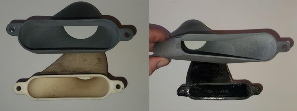 You will also note the much improved quality of the 3D printing on the Driver’s side. My original part was done on a friend’s hobby printer while the new grey-colored parts were printed for me through the very good offices of my former colleagues at HP Labs. The air flow through the center outlets could also be improved, perhaps not as much because there is no way to significantly enlarge the exit hole that feeds these outlets in the evaporator box in my design. However, by replacing the nominal two-inch corrugated hoses that feed the center outlets with a much larger single rectangular duct that feeds both it should be possible to reduce the acoustic impedance that the tube-axial fans are much more sensitive to than are centrifugal blowers, and that should result in improved air flow. You can see some of this from this photo of the holes for the hoses being bored in the transition piece. The combined areas of the two holes is obviously significantly less than the entire area of the side of the adapter piece. 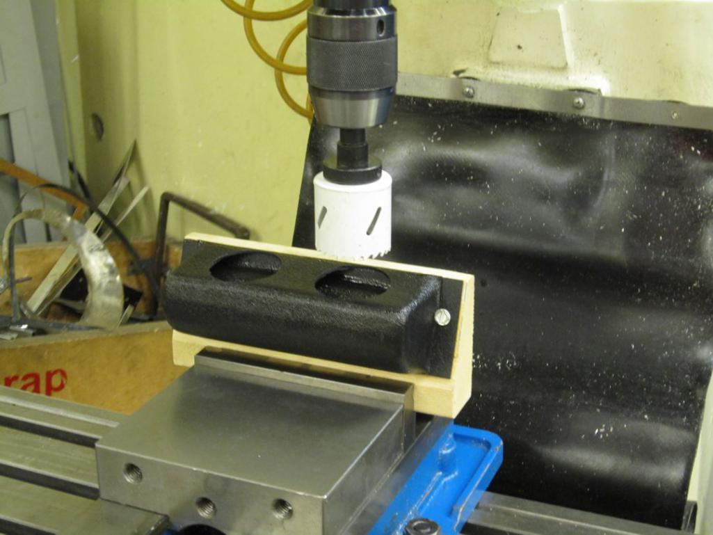 So, I cut a rectangular hole as large as will fit within the size of this output face of this part and built a rectangular duct that preserves this cross-section all the way down to the center outlets. The finished part looks like this: 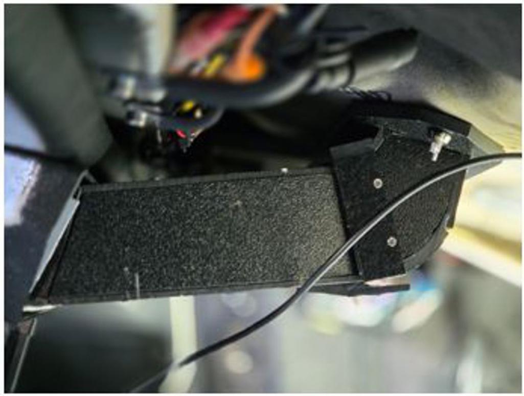 This may seem like a lot of work for a small improvement, but the final measured air flow is just slightly less than a factor of 1.75 greater than before. Improving the air flow downstream from the fans won’t do much good, however, unless the air flow on the upstream side of the fans is increased by a similar amount. Fortunately, there is also a way to do that. The original design had only a single 3 inch diameter recirculation air duct on the driver’s side. I used a single duct because I thought there would be an interference with such a duct on the passenger’s side, but that turned out to not be true. Realizing this, I added a second 3 inch duct on the passenger’s side to roughly double the air flow. With these changes made, the revised evaporator box looks like this from the passenger side on the left and the driver’s side on the right: 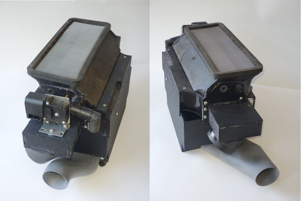 This change of course required an additional opening into the passenger compartment on the passenger’s side: And when installed the modified system looks like this prior to installation of the gas tank: 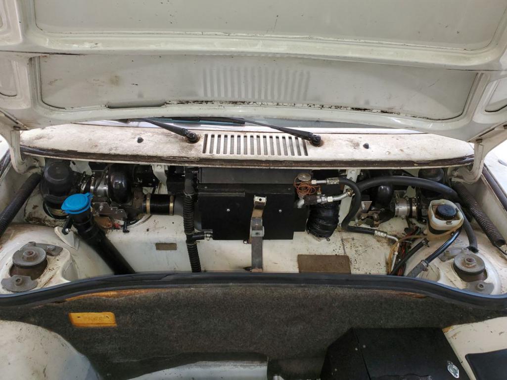 There’s no need to show what the system looks like when all buttoned up as it appears exactly the same as before, which is to say nearly stock. How well did the modifications work? Here is a comparison of measurements before and after: Original System: 76.8cfm Revised System: 140.8cfm So, almost a factor of two, which is roughly what I hoped for, and now actually more than that of my Honda sedan. You may notice that the measurement of the original system, 76.8cfm, is not the number I posted in the earlier thread on the evaporator. I discovered an error in my previous measurement that the current measurements correct. The error effected both the measurements of my 914’s system and that of my Honda sedan, so that comparison is still valid. Item 2, Fix the compressor mounting: This has to do with the arrangement for changing the compressor drive belt, which was poor on the original system. The problem was that in order to mount the compressor high enough to keep it and it’s mounting out of the way of both the fuel injection components and the valve covers the scheme of rotating the compressor about its mounting point to adjust the belt tension resulted in too little adjustment to loosen the belt enough to remove it. This is because the pivot point comes out to be too close to the line joining the centers of the two pulleys involved. The original situation is as shown on the left below and the revision I made, to add an idler pulley and use a longer belt, is shown on the right: Rotating the compressor to make the adjustment was a dumb idea anyway because the hoses attached to it are too stiff to allow very much rotation. The revision required making a new back plate for the shelf that holds the jackshaft so that there is a place to anchor the lower end of the idler arm, plus adding the idler itself. The result, however has been trouble-free and has cured the chronic belt slipping that I encountered before. It’s even accessible, although barely, without having the engine out of the car (see below). 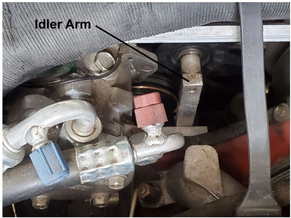 Item 3: Remount the External Oil Cooler Inside the Front Trunk This was not necessary for the AC to function well. In fact, it actually reduced the cooling efficiency but only slightly and not noticeably in using the system. The motivation was the considerable ugly that resulted from my previous scheme for mounting both the condenser coil and the external oil cooler at the front of the car: 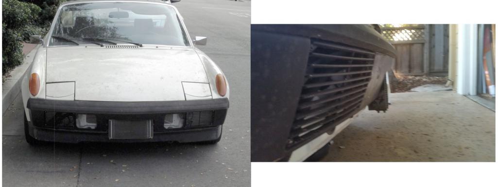 This was all to achieve an air flow situation where the oil cooler got air directly from the front while the condenser coil sat behind it and got its air from openings that allowed air to flow around the cooler and exit underneath the car as did the air from the cooler. The arrangement was as shown below: 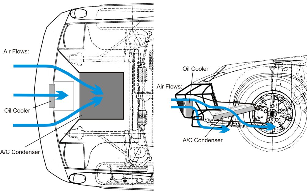 Rather than extending the bumper to cover the oil cooler, I realized it would be possible to move the condenser toward the rear of the car enough to allow remounting the oil cooler inside the front trunk and still have enough room for a scoop that ducts the heated air that passes through the cooler out the bottom of the car so that that air doesn’t also pass through the condenser. The change is as shown below: 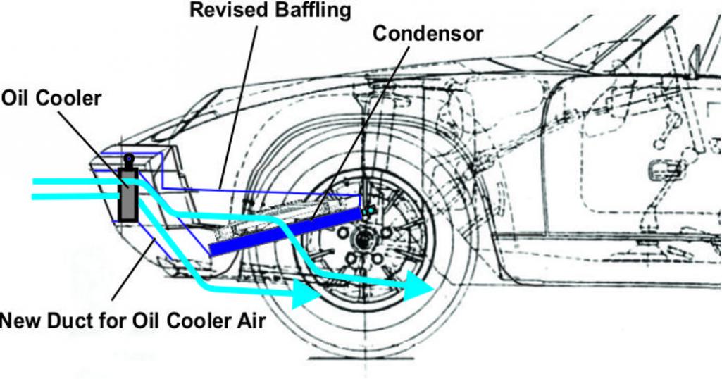 This idea was attractive because it would allow staying with any of the factory bumper variations that are already available instead of trying to fabricate something special, which is something I have little to no experience doing. It would also respect a styling principle that I have found remarkably valid in a wide range of cases. Namely, that attempts to improve automotive styling that you may think is ugly more often than not make it uglier. The origin of the extra room in the front trunk for this was that I cut and reinforced the hole in the floor of the front trunk to match the depression formed into the floor and not to match the condenser coil, which I had not yet identified at that point. 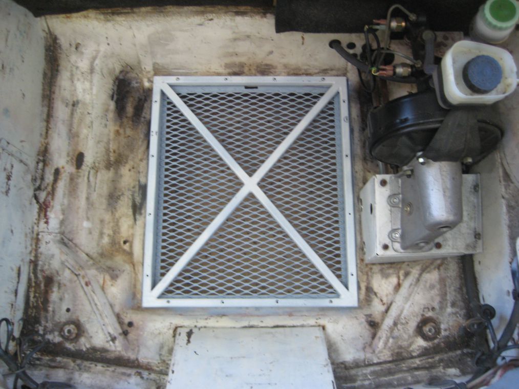 When I settled on the Honda Civic condenser I found that the width of the opening was a close match to the Honda coil, but the length, front to rear, was longer than necessary by about four inches. In the original version I simply covered those four inches with sheet metal, mounting the condenser as far forward as possible. For this version I would move the condenser back those four inches, but in the time since the photo above was taken I changed the brake actuation linkage to the vacuum booster shown on the right and clearing that required also moving the condenser three inches to the left. This would create an additional bend in the path that the air must follow, no doubt causing some loss in cooling efficiency, but I have found it to be nearly imperceptible in actual use. So the new condenser mounting looks like this: 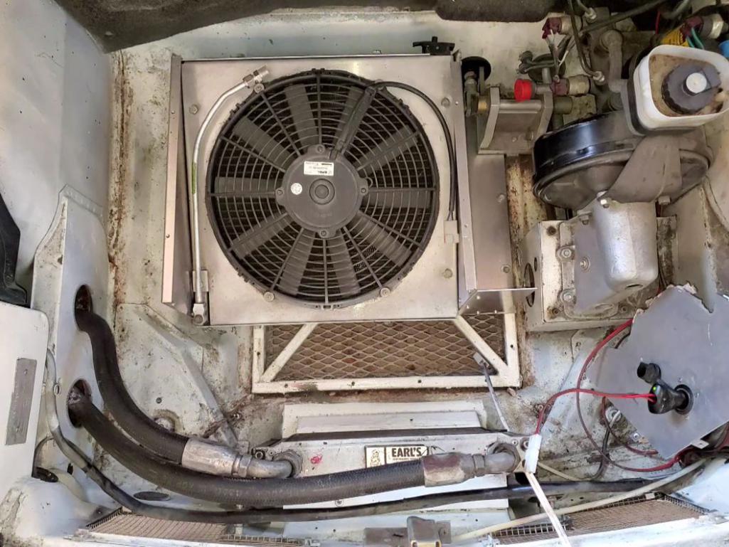 Here you can see how moving the condenser has created the open area at the front of the opening for exhausting the air that will be used to eliminate the air that has passed through the oil cooler, which has already been remounted within the trunk. 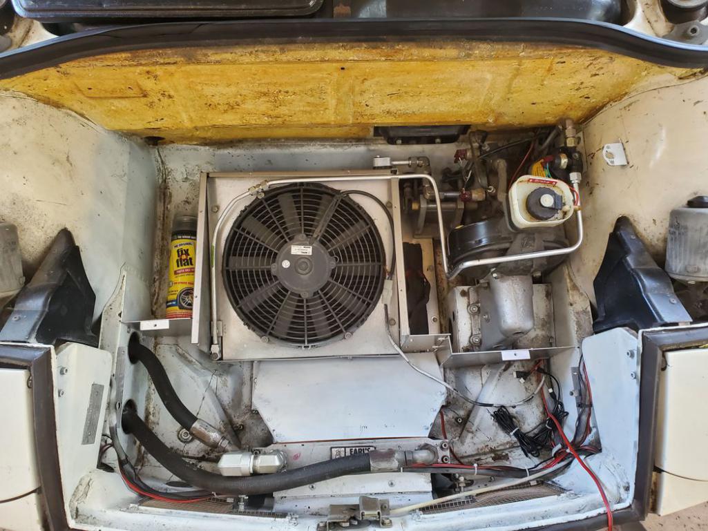 This shows the exhaust duct for the oil cooler air in place as well as a few more of the baffles that will constrain the air that enters through the screened openings in the front wall to exit through the condenser. The side view below shows more effectively the oil cooler exhaust duct. 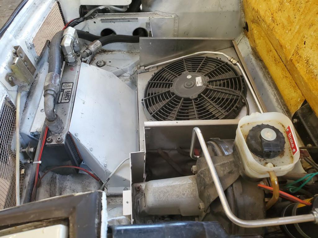 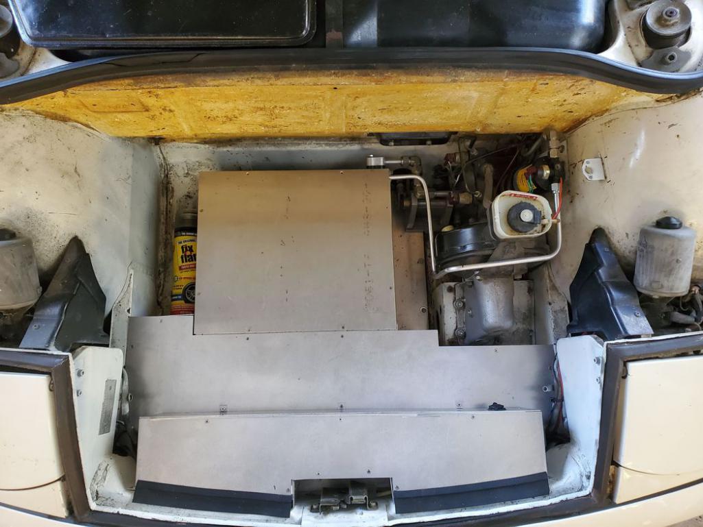 Here the remaining baffles and an enclosure for the brake booster are in place. The flat area behind the box at the front that encloses the upper part of the oil cooler is the same height above the bottom of the trunk as the top of the original spare tire. The cavity beside the condenser to the left neatly holds my larger-than-original tool kit, and the one on the right is just about the right size to store a can of “Fix-a-Flat” now that there is no spare tire. The addition of a removable wooden floorboard makes the trunk ready for upholstery to finish it off and the finished product looks like this: 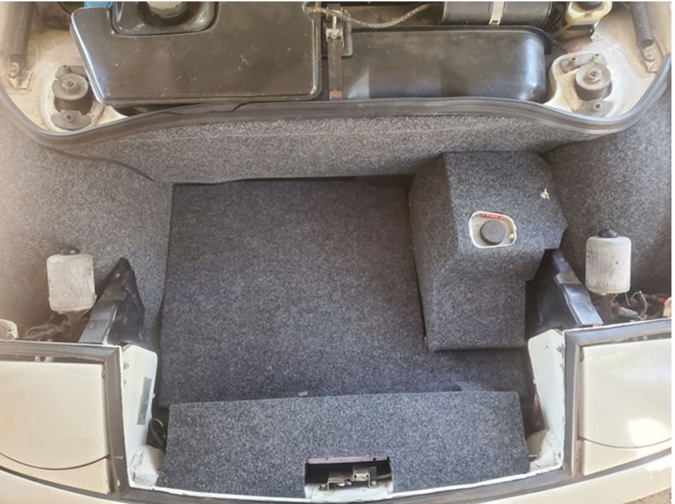 Item 4: Beautify the Front As I mentioned earlier, this now empowered me to go back to a factory bumper configuration, and the result is shown below: 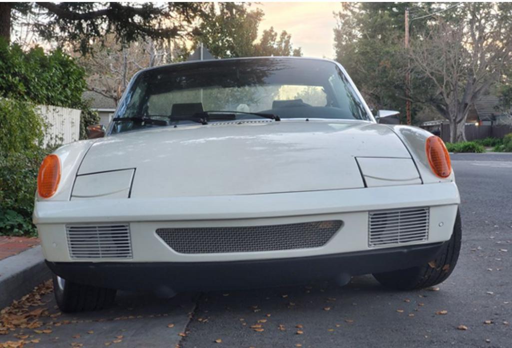 Believe it or not this is the same bumper, the one the car was originally delivered with. I went back to the stock front valence rather than the LE air dam copy I had before because I’ve always liked the look of the valence better, and I’ve probably done all the 100+ mph driving in this car that I’m ever going to. I did the metalwork myself, welding in patches for the former openings, cutting the new central opening, forming the lip for the opening, and welding the flared ends on the valence to match the flares, but I had Yeaman Autobody subsequently straighten and clean up my act and paint everything. The bumper strip atop the bumper is the fiberglass reproduction sold by Carl Rudolph, which I used because I wanted to paint it body color and his part is high quality, smooth, and ready for paint. For me changing the color of this strip away from black has made all the difference in the appearance of the front end. I have never liked the look of that big ugly black strip across the front of my white car and this solves that problem. Item 5: Re-do the Controller for “Period Correctness” I’m not sure just when I got bitten by the “Period Correct” bug, but I did. Perhaps it was when I got far enough along with the project to worry about styling issues rather than just functionality. One of the glaring period incorrect things about the original system was the all-electronic controller, shown below: 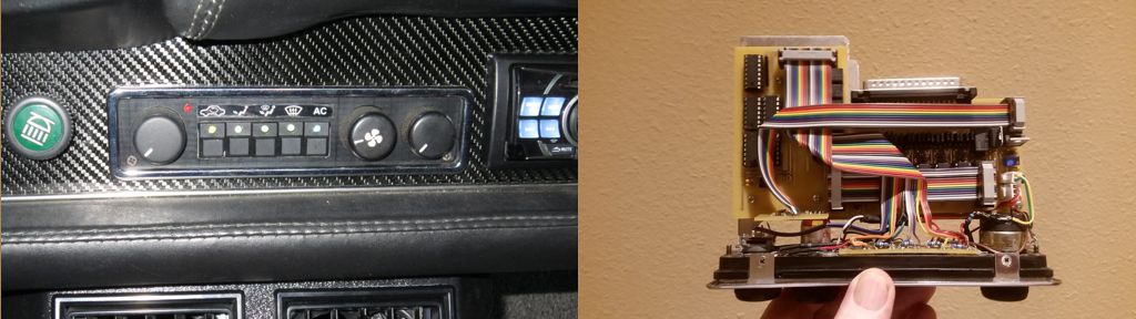 Having used the system now for quite a while, I could see how controls in an automotive setting need to be easily identifiable by touch because you often do not have the opportunity to take your eyes off the road to adjust something within the car. The original controls with stacked levers to control most functions does seem to be better in this regard, but I must confess that I like it mainly just because looks more correct. I looked at re-purposing the original lever control unit to operate my system, but the effort required seemed excessive because the levers themselves take up so much of the available space behind the dash, leaving very little room for the electronics. So I built the controller shown below using 100mm long slide potentiometers to replace the levers. 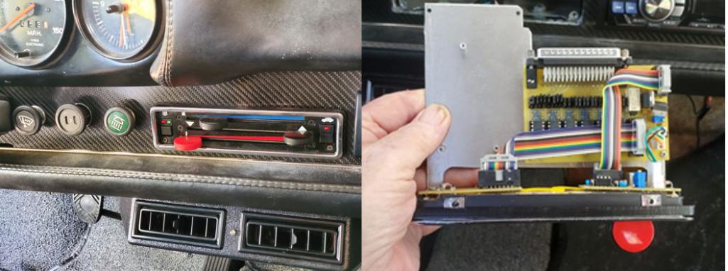 Doing so simplified the controller significantly, as you can see from the picture on the right. I was able to delete the entire PC board on the left, which mostly just implemented the radio pushbuttons. The middle lever controls all four of the flappers that send both heated and cooled air up to the windshield or down to your feet and so now allows continuous variation in that split. The lower lever controls the amount of heated air by varying the position of the butterfly valves in the heater ducts and turns on both the engine-mounted blower and the footwell booster blowers when it’s moved any significant distance to the right of the zero position. The top lever varies the volume of cool air by controlling the fans in the evaporator, and was the most trouble to implement because this control requires a nine-position slide switch rather than a potentiometer. What I wound up doing was using the slide pot as the mechanical basis for the linear motion but just using it to move a small carriage attached to its lever. The carriage moves both a small wiper that shorts together pads on a long thin PC board mounted just above the slide pot to perform the switching and a spring plunger that acts against a long metal strip mounted below with holes that the plunger snaps partially into to define the detent positions for the various fan speeds. The switch on the left controls the AC (on/off) and the switch on the right controls the damper on the fresh air intake (recirc . only/recirc. Plus fresh air). Using the slide pots also provides an easy way to illuminate the controls. They come with an LED (white or red) mounted on the end of each lever. I made knobs of colored plexiglass, smoky grey for the two that are normally black, to fit over the levers and hooked up the LEDs to the illumination power for the other instruments so that they too light up when the lights are turned on. The light from the LEDs makes the knobs glow. |
   |

 
|
  |
Replies
| Shivers |
Nov 3 2026, 04:26 AM
Post
#2
|
|
Senior Member Group: Members Posts: 3,705 Joined: 19-October 20 From: La Quinta, CA Member No.: 24,781 Region Association: Southern California |
Very nice job, I really like the fix on the front bumper. Everything tucked and clean.
So much to look at but the nagging question I have is, in the frunk how on earth did you get the perlon to lay down on those outer wheel wells so nice. I wanted to do it but I wasn't willing to cut and paste. |
 |
|
Posts in this topic


|
3 User(s) are reading this topic (2 Guests and 0 Anonymous Users)
1 Members: seanpaulmc

|
Lo-Fi Version | Time is now: 3rd November 2026 - 05:50 AM |
Invision Power Board
v9.1.4 © 2026 IPS, Inc.