|
|
|
Porsche, and the Porsche crest are registered trademarks of Dr. Ing. h.c. F. Porsche AG.
This site is not affiliated with Porsche in any way. Its only purpose is to provide an online forum for car enthusiasts. All other trademarks are property of their respective owners. |
|
|


| Trekkor |
 Mar 2 2005, 11:47 AM Mar 2 2005, 11:47 AM
Post
#1
|
|
I do things...  Group: Members Posts: 7,809 Joined: 2-December 03 From: Napa, Ca Member No.: 1,413 Region Association: Northern California |
I have the guage in the car and the temp side is wired.
It's the pressure and idjit light that I need help with. New wires are run from the senders to the guage. What wire goes where? I have four wires. One off the idiot sender and three off the pressure sender. Help me help myself. (IMG:http://www.914world.com/bbs2/html/emoticons/wink.gif) Attached image(s) 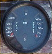
|
   |

 
|
  |
Replies
| lapuwali |
Mar 2 2005, 01:07 PM
Post
#2
|
||
|
Not another one! Group: Benefactors Posts: 4,526 Joined: 1-March 04 From: San Mateo, CA Member No.: 1,743 |
The idea is that the idiot light has +12 on one side of the bulb, and the other side is grounded through the sender. The sender here is just a switch that OPENS above some set pressure, and closes below that. The gauge is similar, except the ground is through a variable resistor that changes resistance (to ground) based on the pressure. The gauge needs a separate "real" ground to act as a reference so it knows how far the pressure sender "ground" is from the "real" ground. The difference is displayed on the gauge. In the two-post VDO sender, one terminal is for the light, one for the gauge, and the ground is through the threads in the sender into the engine block. This oddball sender COULD have a separate ground wire, rather than grounding through the threads. If that's the cause, then one post will be light, one will be gauge, and the third you just ground somewhere. It also COULD ground through the threads and the third wire is +12, which is used by some active device inside the sender. As I said, I've not seen one of those senders, so all I can do is guess. You could try measuring this sender to see what's what. See what the resistance is between pairs of wires (three ways to do this). If one wire is a ground wire, then you'll probably get 0 ohms between two wires and something above 0 between two others and infinite between the last pair. The pair with 0 ohms are the ground and the light switch. The pair with something above 0 are the ground wire and the pressure sender, and the last are between the light switch and the pressure sender. If you think you've got a handle on that, try starting the engine and see how the resistances change. The light/ground wire pair should now show infinite (switch open), the pressure/ground wire pair should show something other than what you measured with the engine off, but it shouldn't be 0 or infinite. The last pair should still be infinite. |
||
|
|
|
||
Posts in this topic
 trekkor 911 oil temp/pressure guage Mar 2 2005, 11:47 AM
 Aaron Cox ok...all the gauges are labeled. they need 3 thing... Mar 2 2005, 12:15 PM lapuwali Three off the pressure sender?
There should be no... Mar 2 2005, 12:22 PM Aaron Cox <... Mar 2 2005, 12:29 PM trekkor The temp side is already dialed htt... Mar 2 2005, 12:31 PM trekkor oh, and the wire colors shown mean nothing. Just f... Mar 2 2005, 12:33 PM lapuwali I've never seen a pressure sender that looked ... Mar 2 2005, 12:44 PM trekkor Soooo, in my pic, let's say the white is groun... Mar 2 2005, 12:45 PM ! The gauge I had did not work with the sender on th... Mar 2 2005, 12:47 PM ArtechnikA need more data...
what year is your combo gauge? ... Mar 2 2005, 12:58 PM Dave_Darling This is from a six-cylinder engine, right?
As I r... Mar 2 2005, 01:11 PM Aaron Cox the hot tip is to get the vdo dual post sender. on... Mar 2 2005, 01:13 PM ArtechnikA http://www.914world.com/bbs2/ht... Mar 2 2005, 11:45 PM ArtechnikA Mar 3 2005, 05:48 AM lapuwali Mar 3 2005, 10:37 AM trekkor http://www.914world.com/bbs2/ht... Mar 3 2005, 10:51 AM ! Call Dave at GPR....800-321-5432 ext 502 Mar 3 2005, 10:57 AM
Aaron Cox ok...all the gauges are labeled. they need 3 thing... Mar 2 2005, 12:15 PM lapuwali Three off the pressure sender?
There should be no... Mar 2 2005, 12:22 PM Aaron Cox <... Mar 2 2005, 12:29 PM trekkor The temp side is already dialed htt... Mar 2 2005, 12:31 PM trekkor oh, and the wire colors shown mean nothing. Just f... Mar 2 2005, 12:33 PM lapuwali I've never seen a pressure sender that looked ... Mar 2 2005, 12:44 PM trekkor Soooo, in my pic, let's say the white is groun... Mar 2 2005, 12:45 PM ! The gauge I had did not work with the sender on th... Mar 2 2005, 12:47 PM ArtechnikA need more data...
what year is your combo gauge? ... Mar 2 2005, 12:58 PM Dave_Darling This is from a six-cylinder engine, right?
As I r... Mar 2 2005, 01:11 PM Aaron Cox the hot tip is to get the vdo dual post sender. on... Mar 2 2005, 01:13 PM ArtechnikA http://www.914world.com/bbs2/ht... Mar 2 2005, 11:45 PM ArtechnikA Mar 3 2005, 05:48 AM lapuwali Mar 3 2005, 10:37 AM trekkor http://www.914world.com/bbs2/ht... Mar 3 2005, 10:51 AM ! Call Dave at GPR....800-321-5432 ext 502 Mar 3 2005, 10:57 AM type47fan Mar 3 2005, 08:19 PM
 |
1 User(s) are reading this topic (1 Guests and 0 Anonymous Users)
0 Members:

|
Lo-Fi Version | Time is now: 8th June 2024 - 08:56 PM |
Invision Power Board
v9.1.4 © 2024 IPS, Inc.