|
|
|
Porsche, and the Porsche crest are registered trademarks of Dr. Ing. h.c. F. Porsche AG.
This site is not affiliated with Porsche in any way. Its only purpose is to provide an online forum for car enthusiasts. All other trademarks are property of their respective owners. |
|
|


| lapuwali |
 Sep 19 2005, 05:05 PM Sep 19 2005, 05:05 PM
Post
#1
|
|
Not another one!  Group: Benefactors Posts: 4,526 Joined: 1-March 04 From: San Mateo, CA Member No.: 1,743 |
Included here is a "minimum" wiring diagram. This is good enough for a racer, and good enough for a minimal street car (daylight, no rain). I'll be building up the diagrams bit by bit over time. I'm not following the OEM wiring colors exactly, as I'm not going to use "tracer" wire (too hard to get in small quantities). But the general scheme will be the same.
This diagram shows my car as it sits now, and it starts and drive (carbs, btw). The next diagrams will show things like gauge hookups, lights, misc, and EFI. I'll also be posting tips on constructing your own harness, like which connectors to use, tools, techniques. Attached image(s) 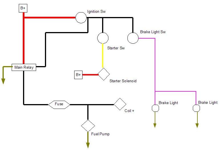
|
   |

 
|
  |
Replies
| lapuwali |
Sep 19 2005, 05:19 PM
Post
#2
|
|
Not another one! Group: Benefactors Posts: 4,526 Joined: 1-March 04 From: San Mateo, CA Member No.: 1,743 |
When removing the OEM harness, it all needs to be pulled "towards" the fusebox. Everything should be disconnected in the front trunk (lights, horn, headlight motors, wipers, front blower) and all of the wiring pulled down through the grommeted hole near the left A-pillar, directly in front of the driver. The rear trunk wiring should be disconnected and pulled towards the relay board. The relay board should be disconnected and removed. The wiring from the various bits of the engine to the 12-pin connector on the relay board (the one towards the rear of the car) is completely separate. The section from the relay board and battery forward has to go down through the hole in the front engine shelf, then forward through the firewall and the center tunnel.
The wiring behind the dash disconnects at or very near the steering column. For the early cars, there's one big connector hidden up behind the dash that looks like a relay board connector. This is mounted with a slot connector to the dash itself, to the right of the steering column. On the later cars, there are several connectors at the bottom of the steering column. The wires from the heater controls are all just spade terminals. You'll be tempted several times to just pull out the snippers and start cutting wires. If the wire insulation is still flexible and not horribly faded, the wire can be reused in a new harness, so try not to cut it. New wire is quite pricey. Proper automotive grade (heat and oil resistant insulation) wire can easily run $300 or so for enough in enough colors to complete a harness. Connectors, however, generally should be discarded, so don't feel too bad about cutting off connectors you can't feed through a hole. |
|
|
|
Posts in this topic
 lapuwali Rewiring project thread Sep 19 2005, 05:05 PM
 Mueller I thought it was illegal to not have operating win... Sep 19 2005, 05:13 PM lapuwali <... Sep 19 2005, 05:20 PM Mueller ... Sep 19 2005, 05:24 PM lapuwali This diagram is of the charging system. Pretty si... Sep 20 2005, 09:50 AM goose2 Great thread James...very helpful.
 |
1 User(s) are reading this topic (1 Guests and 0 Anonymous Users)
0 Members:

|
Lo-Fi Version | Time is now: 2nd July 2025 - 12:09 PM |
Invision Power Board
v9.1.4 © 2025 IPS, Inc.
| All rights reserved 914World.com © since 2002 |
|
914World.com is the fastest growing online 914 community! We have it all, classifieds, events, forums, vendors, parts, autocross, racing, technical articles, events calendar, newsletter, restoration, gallery, archives, history and more for your Porsche 914 ... |