|
|
|
Porsche, and the Porsche crest are registered trademarks of Dr. Ing. h.c. F. Porsche AG.
This site is not affiliated with Porsche in any way. Its only purpose is to provide an online forum for car enthusiasts. All other trademarks are property of their respective owners. |
|
|


| DougC |
 Oct 3 2005, 09:09 AM Oct 3 2005, 09:09 AM
Post
#1
|
|
Senior Member  Group: Members Posts: 949 Joined: 6-July 04 From: Dallas, TX Member No.: 2,307 |
I have a problem where I get a major spark when attaching the battery cables to the battery. Clay Perrine pointed out to me that it's the heavy RED wire that's attached to the Starter (same place as the battery cable) and runs up to the back of the alternator. Clay suggested that this red wire was hooked to the wrong post on the altenator. OK, I removed the complete CIS injection unit and peeled back the engine shoud. The wires were hooked up to the alternator like in Wayne Dempsy's book, the pictures I took upon disassembly were lost so I had to use the book for this. I'm using a newly rebuilt Marchall alt. with external regulator. Here's a breakdown of how I have it wired:
(posts are clockwise from the top) "+G1" or "+61" = blue wire "B+" = Red wires [one thick, one thinner] "another B+" = short ground strap from engine case "DF" = black wire with spade end "D-" = 3 small brown wires "D." = un-used Where have I gone wrong? Doug C |
   |

 
|
  |
Replies
| Porsche Rescue |
Oct 5 2005, 02:42 PM
Post
#2
|
|
Saving and Enjoying Old Porsches Group: Members Posts: 2,978 Joined: 31-December 02 From: Bend, Oregon Member No.: 64 Region Association: None |
Just so we don't muddy the water too much: What I am describing is for a '74 914-4 (my car) which is converted to a six using the 911 alternator and the 914-4 relay board and voltage regulator. I have factory wiring diagrams. If your car is another year (probably the same anyway), let me know.
The wire to the gen. light (red) on your dash should be blue. It is directly connected to the D+ wire from your alternator through the relay board/voltage regulator. The blue wire originates at the relay board (terminal 2 of the 14-pin connector). It connects to the D+ somehow in the relay board/voltage regulator. When you turn on the key it lights and goes out when alternator starts to work. The light bulb in the gauge has the blue wire and a red with white stripe connected to it (same circuit that powers other instruments). The red/white is powered with the ignition switch. In order for the light to operate, you must have the three wire plug from the alternator correctly connected to the relay board. The plug should have the D+ wire from the alternator in the forward position. Here is a pic of my relay board and connector. The red in the connector is D+, brown is D- and green is DF. The large connector on the front is the 14 pin to the chassis. You can unplug it and read the terminal numbers on the underside of the plug. Term. 2 should show continuity to the bulb in the "G" hole on the gauge(blue wire). Attached image(s) 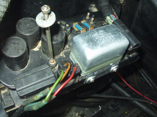
|
|
|
|
Posts in this topic
 DougC Help, Alternator Hook up for the /6 Oct 3 2005, 09:09 AM
 Porsche Rescue I recently wired a Bosch alternator on my six conv... Oct 3 2005, 09:44 AM DougC Jim, I moved the ground to the fan frame body just... Oct 3 2005, 10:37 AM Porsche Rescue Sorry, but I am not too knowledgable on electrical... Oct 3 2005, 10:52 AM DougC I'm using the relay board..and the connector t... Oct 3 2005, 11:00 AM Cap'n Krusty "B+" is "B+". Why would you EVER hook it up to gr... Oct 3 2005, 11:03 AM Porsche Rescue The small red is the D+ and does not connect to B+... Oct 3 2005, 11:14 AM Porsche Rescue I just looked at Dempsey's book, page 26. Tota... Oct 3 2005, 12:02 PM ClayPerrine Doug,
Start with unhooking everything but the b... Oct 3 2005, 12:04 PM Kerrys914 My turn http://www.914world.com/bbs... Oct 3 2005, 12:21 PM Root_Werks ... Oct 3 2005, 12:30 PM DougC "B+" is "B+". Why would you EVER hook it up to gro... Oct 3 2005, 12:44 PM Jeffs9146 Here is a photo of my alt.
Jeff
PS: this is from... Oct 3 2005, 01:00 PM DougC Doug, are you running your wires to the factory 91... Oct 3 2005, 01:01 PM DougC Thanks for the picture Jeff. Unfortunately for me,... Oct 3 2005, 01:10 PM Jeffs9146
Porsche Rescue I recently wired a Bosch alternator on my six conv... Oct 3 2005, 09:44 AM DougC Jim, I moved the ground to the fan frame body just... Oct 3 2005, 10:37 AM Porsche Rescue Sorry, but I am not too knowledgable on electrical... Oct 3 2005, 10:52 AM DougC I'm using the relay board..and the connector t... Oct 3 2005, 11:00 AM Cap'n Krusty "B+" is "B+". Why would you EVER hook it up to gr... Oct 3 2005, 11:03 AM Porsche Rescue The small red is the D+ and does not connect to B+... Oct 3 2005, 11:14 AM Porsche Rescue I just looked at Dempsey's book, page 26. Tota... Oct 3 2005, 12:02 PM ClayPerrine Doug,
Start with unhooking everything but the b... Oct 3 2005, 12:04 PM Kerrys914 My turn http://www.914world.com/bbs... Oct 3 2005, 12:21 PM Root_Werks ... Oct 3 2005, 12:30 PM DougC "B+" is "B+". Why would you EVER hook it up to gro... Oct 3 2005, 12:44 PM Jeffs9146 Here is a photo of my alt.
Jeff
PS: this is from... Oct 3 2005, 01:00 PM DougC Doug, are you running your wires to the factory 91... Oct 3 2005, 01:01 PM DougC Thanks for the picture Jeff. Unfortunately for me,... Oct 3 2005, 01:10 PM Jeffs9146 
