|
|
|
Porsche, and the Porsche crest are registered trademarks of Dr. Ing. h.c. F. Porsche AG.
This site is not affiliated with Porsche in any way. Its only purpose is to provide an online forum for car enthusiasts. All other trademarks are property of their respective owners. |
|
|


| groot |
 Nov 14 2005, 02:36 PM Nov 14 2005, 02:36 PM
Post
#1
|
|
Dis member  Group: Members Posts: 896 Joined: 17-December 03 From: Michigan Member No.: 1,444 |
Some of us have been discussing the 914 rear suspension offline and I measured my toe curve yesterday. I figured I'd share it with the club for discussion.
The axle height scale is in inches and the zero is with the arm level. Attached image(s) 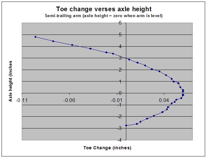
|
   |

 
|
  |
Replies
| groot |
Nov 19 2005, 10:51 AM
Post
#2
|
|
Dis member Group: Members Posts: 896 Joined: 17-December 03 From: Michigan Member No.: 1,444 |
Or I could just post the text.... duh....
Car Suspension and Handling, Second Edition Written by Donald Bastow Penntech Press 6.9 TRAILING AND SEMI-TRAILING ARMS The fundamental difference between trailing and semi-trailing arms is that the axis of the former is at right angles to the car centre line; this implies that there is no change, in end view, of the angle of the wheels with suspension movements. The semi-trailing arm, so far confined to examples where in plan view the axis of oscillation of the arm meets the vertical plane of the wheel axes towards or beyond the other rear wheel, necessarily introduces some swing axle effect. Although it is generally considered that the instantaneous centres are where the arm axis intersects the vertical planes of the rear wheel axes across the car and fore and aft, this is not strictly true. The actual path of any point on the wheel, in side or end elevation, is an ellipse and the instantaneous centre for that part of the ellipse can be found by known methods. The knowledge that roll-steer effects are at a minimum when the semi-trailing arm axis is parallel to the ground is useful but we need to know more. For this we must study how toe-in changes on bump and rebound vary with changes in position of the semi-trailing arm axis, in plan view and in the angle which the axis makes with the ground. A basic case has been chosen in which the semi-trailing arm axis is at road wheel centre height, meets the rear wheel axis of the car at one wheel plane, point 2, and intersects the plane of the wheel whose movements are being studied 400 mm forward of its centre, point 1. Figure 6.19 shows this. An alternative plan position shows the semi -trailing arm axis meeting the rear wheel axis at twice the car track from the wheel being studied, point 2A. Points 3, the wheel centre, and 4, 100 mm away along its axis, are for calculation purposes to obtain the toe-in changes. The heights of points 1 and 2 in Table 6.1 define the axis changes studied, in height and inclination to the ground: rising to the front, dropping to the front, high or low; and parallel to the ground but above or below the original position. The resulting roll centre heights are also shown; they indicate the amount of sideways 'scrub' of the contact patch with bump and rebound movements. Anthony Best Dynamics Ltd. has kindly computed the results and its co-operation is gratefully acknowledged. The results are summarised in Fig. 6.20(a). Figure 6.20(B) shows the camber changes. Fig. 6'20 (a) Here the results of the calculations in terms of change of toe-in with bump and rebound movement are shown. There are effectively no differences between cases 1, 7 and 8 where the axes are parallel to the ground but at different heights. Cases 2 and 4, axes up towards the front but at different heights, are also effectively the same as each other but now favour "bump at the expense of rebound. The converse applies to cases 3 and 5, where rebound is favoured. Case 6, axis parallel to the ground and more nearly so to the rear wheel axis, halves the toe-in changes. Fig. 6.20 (B) The camber changes depend only on the distance from the affected wheel to the intersection of the axis and the vertical transverse plane containing the wheel axes Within the limits studied, i.e. axis height::l: 20 mm parallel to the ground, and a height change of 20 mm in sloping axes, nose high and nose low, and bump and rebound movements each of 75 mm, axis height does not affect the results (to two significant figures). The nose high axis position favours bump movements, and vice versa. Camber changes depend only on the distance from the studied wheel to the intersection of the semi-trailing arm axis, point 2, with the transverse vertical plane containing the undefIected rear wheel axes. From the trends within the range studied, we see that a sufficiently large nose-high axis angle wilI give toe-out on bump and toe-in on rebound; and again vice versa. If the distance between wheel arches is important it must be remembered that the introduction of any swing axle effect has to be accompanied by an increase in the track to maintain that distance between wheel arches. |
|
|
|
Posts in this topic
 groot Toe Curve for Semi-trailing arm Nov 14 2005, 02:36 PM
 MattR http://www.914world.com/bbs2/... Nov 14 2005, 02:45 PM lapuwali I presume on that graph positive numbers are for b... Nov 14 2005, 03:07 PM groot Sorry, I meant to explain more, but I had to run o... Nov 14 2005, 03:23 PM Racer Chris Based on the graph it appears that your car has th... Nov 14 2005, 10:08 PM groot No inference required... it's right there on t... Nov 15 2005, 08:40 AM Racer Chris Nov 15 2005, 05:04 PM Brett W You will increase the scrub by changing the pivot ... Nov 15 2005, 07:50 PM brant wow...
great thread Kevin!
I'm going to ha... Nov 15 2005, 11:30 PM Racer Chris <... Nov 16 2005, 07:09 AM groot I met with Finch the other day for a few hours and... Nov 16 2005, 08:26 AM Racer Chris Nov 16 2005, 09:01 AM groot Good point!!
Let's hope there are no ... Nov 16 2005, 09:11 AM groot Nov 16 2005, 09:28 AM Brett W
MattR http://www.914world.com/bbs2/... Nov 14 2005, 02:45 PM lapuwali I presume on that graph positive numbers are for b... Nov 14 2005, 03:07 PM groot Sorry, I meant to explain more, but I had to run o... Nov 14 2005, 03:23 PM Racer Chris Based on the graph it appears that your car has th... Nov 14 2005, 10:08 PM groot No inference required... it's right there on t... Nov 15 2005, 08:40 AM Racer Chris Nov 15 2005, 05:04 PM Brett W You will increase the scrub by changing the pivot ... Nov 15 2005, 07:50 PM brant wow...
great thread Kevin!
I'm going to ha... Nov 15 2005, 11:30 PM Racer Chris <... Nov 16 2005, 07:09 AM groot I met with Finch the other day for a few hours and... Nov 16 2005, 08:26 AM Racer Chris Nov 16 2005, 09:01 AM groot Good point!!
Let's hope there are no ... Nov 16 2005, 09:11 AM groot Nov 16 2005, 09:28 AM Brett W 
